-
Posts
5,758 -
Joined
-
Last visited
Content Type
Profiles
Forums
Events
Everything posted by Gixer1460
-
How did you swop carbs around? Alternate rack or break the rack up and swap bodies around? Surprised it ran at all swopping 1 and 2 leads around as it would make ignition 180 degrees out ! ! ! You can swop 1 and 4 or 2 and 3 - no other combinations are correct.
-
As said, its normal and if you look, there is a bloody great big hole in the casing that you can see the crankshaft through - for drainage. This will have nothing to do with poor starting - look elsewhere LOL.
-
Given your OSS board name , I assume this isn't a boosted application?
-
Using eyeball measuring the 'el gringo' adapter and short filter don't appear any shorter than a std HiFlo HF138 filter @ 64mm ! ! ! This would seem to be a reasonably priced remote filter kit ..... https://www.Eblag.co.uk/i/112553893410?chn=ps
-
Wow - more of a gap than I thought - seeing the pictures, I concur with my learned friends evidence and support his conclusion m'lud - Guilty as charged!
-
Looks a very conservative curve - pretty much most engines have all the timing in by 4000 rpm tops. The extended curves possible with the Dyna 2000 never made any discernible difference on any engine i've seen.
-
Odd ! There isn't usually enough clearance between the rotor and the vanes to injest a whole screw head - usually swarf, maybe a thread?
-
If it makes you feel better, my 1460 GSXR is still using a std cut 'M' gearset!
-
The cup over the end of the screw is a neat idea - saves the threads getting mullered!
-
Certainly not but it is a nice thing to have - missing a gear through bad engagement or slipping out is never wanted.
-
Yeah I can see the problem! I know the ACU make the lanyard kill EVERYTHING electrical - we used to just kill the electrics to the ignition ie. to kill the engine but fuel pumps and nitrous caused issues - can't imagine why LOL! You'll have to seperate the general electrics from the starter electrics. The general electrics will be switched 'on' via a normal 30 amp relay and the lanyard. Looking at the relay terminals you have 85, 86, 87 and 30 and these will be connected as follows, 30 - 30 amp rated cable to battery, 85 - to chassis / battery negative via the lanyard, 86 - 12v feed from battery and 87 - feed to general electrics via fuse box (ignition, fuel pump, nitrous etc) As regards the starter i'm assuming you have a push button to spin the starter? If so, you take a wire from the ign. feed to the kill switch and from the other side down to the ign. ecu and the coils. Also from this side (usually internal to the switch) is a feed to one side of the starter button, the other runs down to a specific starter solenoid (a type of relay). Starter solenoids are earthed via their metal mounting to the chassis. The starter solenoid will have two big screwed connections - one side goes to battery and the other goes to the starter motor - both in heavy gauge cable 150+ Amp rated. Lots of words but it is quite simple.................really LOL!
-
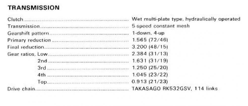
Clutches 1052 / 1127 are essentially the same parts although the later 1127 changed their springs to diaphragm type (and the primary gears are different). They are both capable units and can withhold upto 160-180hp N/A hp............ Turbo torque does them in at much lower hp in my experience. If N/A and application as described, some HD springs should cope - racers like the 4 coil spring type clutch from the 1052 motors as it is more 'tunable' but both will work. If a turbo was fitted then a lock-up is almost mandatory but you may have to cut holes in that nice fairing to accommodate LOL!
-
What do you need to know - if you;ve got the parts, I can explain the method - its not difficult. Good first outing - watching the video I thought you jumped but just excellent RT! Well done on the Round Win.
-
Surely impossible as the pressure size isn't a closed system - the regulator only bleeds off excess pressure doesn't hold it / back it up completely plus there would be other instant damage to bearings / cams etc with no oil flow?
-
That would explain an awful lot! So possibly although the papers say one thing, a previous owner has fitted an alternative engine that looks identical to the original - and if it pulls as you say this is a likely scenario! If you can lift the cam cover to see the cam lobes and cam chain type will give a definitive answer. Also see what the capacity marking on the back of the barrels will give it away - 1127 / 1157? Grey or Black engine colour?
-
Yeah good idea - the only things that won't seize will be the piston rings LOL!
-
That equals about 84hp ! ! ! That's about 40 - 50hp down on the 'full fat' versions! 36mm carbs will happily support 145hp so unless they have the restricted lift tops and severe down jetting - its not there. Exhausts can be restricted - washers or other baffles to make back pressure. Ignition mapping could have been played with by the factory - rev limiter / range restricted / ignition timing. Really soft cams is an option - especially with that amount of loss. Where in the world are you - may give a clue?
-
No adjustment as such - being hydraulic it is supposed to be fairly well self adjusting - which means its either assembled wrong, its a plate short in the stack, there is air in the system or multitude of other things!
-
No - those don't have the spring location peg, and are a lot shorter.
-
-
-
There is ! ....................................... most of the oil pump is in it LOL!
-
Who says they are aluminium? Just says ltwt., so are potentially Ti - I'd rather Ti than two alloys slowly welding themselves together and then twisting the head off!
-
I don't know what section its posted in! - my browser only shows new posts not where they come from!
-
Totally agree with your diagnosis - Its a bit of weight hanging on a relatively weakly attached tube, add in vibration and bumps and classic weld cracking. Either plate over the junction or add a flange brace between the two pipes - i'd add multiple TIG passes to build up joint section.


