nlovien
-
Posts
622 -
Joined
-
Last visited
Content Type
Profiles
Forums
Events
Everything posted by nlovien
-
thats my coat !
-
bloomin ek this can really do your head in trying to think out CV carbs with a variable positive pressure supply - home work time but i'll ramble on anyway you got holes to create a pressure diff to enable lift and you got holes to bleed off ( balance ) to enable a controlled lift inline with fueling needs bigger balance holes = quicker equalisation = no lift when it does - too small holes here and it lifts too quickly - out of sync with the carb jetting circuits - you would have thought by going down main jet - if it was too small holes i.e. getting a main jet slug of richness too early, you should have seen more improvement with smaller mains - ok then is it as you suspect = holes too big, balance too quick - slide not lifting to enable transition to mains - makes sense since you didn't get a measured response by lowering the mains - i.e. is it ever getting to the main jet - wonder if you removed it completely would you see any difference on the dyno ? - no if all its doing is fluttering around the needle fueling only - so suggests smaller balance holes bit I can't get my head around is pressurising the venturi - this also pressurises the negative pressure to the top of the piston via the engine vacuum route = the press diff hole - so i'm thinking your relying on positive venturi pressure to lift from bottom versus engine draw to suck from top as said i'm guessing as I go -- anyway -sooo in this case you want to vent the top of piston to atm. to create press diff to enable lift - now again though - if the balance holes are too big - but now relative to the atm vent hole size then its like above ok so you need to match the equalising hole size to the atmospheric vent size, the bigger the vent is relative to the equalisation the quicker it will lift - but it needs to sustain boost to achieve this - it can't sustain boost if it ain't working hard and it can't work hard if you can't get it to transition via lift from N/A to positive pressure and it will not achieve this if the vent size is too big for the engine vacuum to work holy shit this can get complicated - but the same point seems to keep coming back - smaller equalisation holes = plug off / reduce the holes in the slides i need a dram
-
+1 for ignitech - got their 2D system - and a dyna 2000 on another bike -both do the same job - ignitech does it cheaper however i'll be swapping for their 3D unit - TBH in this day and age we'd be mad not to - its all gain gain via not suffering partial throttle ignition hold back that you get with a fixed 2D system and yi can dial in retard to aid starting big CC high comp engines whats not to like about it ??? - we need more folks doing this - writing the maps so the rest of us can plagiarize
-
you must have picked up the broken window glass
-
this ones not quite finished - once they fit a set of knobbly trail bike tyres - job done there is a simple style that these bikes work brilliantly with - bike of the month sept and April 2017 are two nice examples
-
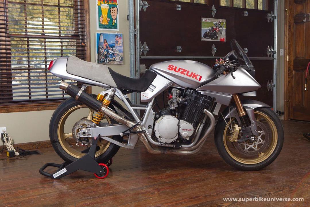
nice one - this version of the GSX, for me is the one in the background that deserves more respect - best style out of the lot
-
brilliant - its a love hate thing that is a key reason why we torture ourselves with these bloomin bike things - we hate them when they don't work, but we love them all the more when we manage to sort it - Robert Pirsig's buddy with the BMW doesn't know what he's missing
-
i'd be checking that when idle the throttle cam is 100% sure closing against the idle stop - not hanging on the cable also - my previous comment ref: ilde screws was misleading - on these carbs the idle adjustment screws are kinda like a mini throttle - they are not mixture adjustment screws like on some other carbs - they adjust how much of the mixture goes in -- sooo if your say at 3/4 turn adjustment close it down further - say down to 1/4 turn only - ok it will not idle, so now open the throttle cam via the main idle adjustment screw = basically your changing the relationship between idle jet and throttle cam - see if this helps - and try it the other way i.e. more idle adjustment screw / less throttle cam but always ensuring the cam does stop against the - stop another thing to check - if you've got filters fitted make sure nothing is blocking the idle air jets at the mouth of a carb venturi edit: just had a play with this - if you find you've got a stumble just as you pick up throttle then you've wound the idle screws in too far - on my AFR gauge it idles nice at almost bang on 14 but if you then open the throttle it goes to 20+ = open the idle screws up
-
should be, have a close look at the spring on the shaft - you'll see a choice of pegs on the alloy casting for the spring end loop to fit over
-
No Oil to Cams after dryblocking and top end oiler kit install
nlovien replied to TiZiK's topic in Oil Cooled
I can see surging losing oil pressure no issues there, I can't see more pressure preventing it mikeyd you've listed some interesting thoughts on this or more specific to crank failure I can see fitting a better quality - more accurate relief valve as a good fix ( known fix on another engine type where its the factory relief valve that,s dodgy - not so much the pressure) I can see horrible things happening to the oil - like foam / aeration causing momentary pressure loss ( known crank destroyer on another type of engine) - could this be related to how the turbo oil return feed is routed ? I wouldn't like to be putting this into the sump anywhere near the oil pick up without thinking about it - can see how this could cause foaming due to the heat of the oli from the turbo + the rapid expansion into the large diameter vent pipe = vapourised oil versus liquid ??? - dunno, known issue with them 4 wheeled things -
with the carbs off - take a look at what spring return your using - you can select more / less by preloading the return spring, see fi you can sort the hanging throttle by being more positive with returning the throttle by hand i.e. using the return cable - might be your on a softer return spring setting and need a bit more to help the slides seat back
-
the choke valves are the ones linked to the choke knob - horizontal front of main body - i've seen these sticking partially open on mikuni's tend to find 1/2 to 3/4 turn on idle screws is a good start - initially aim for "will it run" on these alone at the smallest no. turns - note BE CAREFULL with these = prone to jamming the tips into the venturi then shearing them off leaving the tip plugging the idle circuit port its either no. 2 or 3 ( dam't did this a few weeks back and can#t recall - is this early signs of dementia) that is the non adjustable slide = so you set your throttle stop to this one - i.e. adjust the stop until this slide doesn't drop anymore - then take up the stop until it just moves the slide - then set the other x 3 to match with this set and the idles say 3/4 turn - see if the bike will idle after warming and choke off - without fitting the throttle cables - this is my 1st test and I don't go any further until I find out why not - try and avoid too much winding in the throttle stop adjustment to adjust the idle - a wee tweak only - once you've got a reasonable idle adjust the idle screws 1/4 at a time and observe for the idle speed changing - goes higher keep opening until it starts to drop - goes lower do opposite - simple on paper - can be a pain as the engine heats up but if your getting this response thne you know the basics are good, your confident there's no leaks etc.. another thing I do when setting these up is I have a throttle drum i've sanded down to a smaller diameter = more wrist movement to open the carb = less sensitive for the 1/4 - 1/2 - 3/4 - full marks you use to give the key fueling part that's prominent once your confident you have a proper working carb with no leaks on an engine that has reasonably balanced compression and the valve gaps are good = a great help is to fit a lambda sensor and gauge - helps with the guess work
-
i'd 1st check there is no sign of fuel wetting in the venturi ( and anything coming out the overflow )- i.e. leaking float valves and i'd remove the pumper rod ( easy job) so yir focusing on the jets check the choke valves are closing and seating check the cables are letting the slides fully close (i.e. there is some cable slack and the throttle cam is going back against the stop i.e. all the things that might be causes excess fuelling- oh and put it back to the setting that it was dyno ed at whilst doing this so you have a good base setting
-
seems he's not been put off too badly, the big sell up is to fund his new hobby - car racing - must be some car!
-
the pipe is a bit better looking from other pics - note the lack of footbrake ? - its via the thumb worth having a peek at some of the bikes he is selling - he recently sold an ex motgp CRT1000 suzuki - priced at $35K - look for superbikeuniverse
-
came across this for sale as part of a big bike collection - interesting build - its a 400 with a well tuned 1260cc motor to push it along - got to be a lot of fun being small with big lungs and some decent running gear - asking is $15K ouch - probably some flex in this, would be a fair guess that its probably near new build condition - anyway - its a nice twist on the Katana theme

- 16 replies
-
- 10
-

-
+1 - these pics are handy for any bike build
-
has it been sitting a while dormant - or has it just decided to stop playing
-
if yir baws are big enough - you got plenty their to have a heck of a lot of fun with
-
good suggestions - yi get unusual results with carbs - check yir ignition - not so much the timing but the strength of it - corroded connectors, weak coils - running the ignition power feed via the switch gear - plug gaps out etc... - TBH if there's any part of this circuit that's original GS then it will be needing TLC
-
I haven't done this myself ( had it done) however you got it - the finish ream after installation is key + parallel alignment of the ream relative to the big end
-
can also confirm on fitting bronze sleeves into small ends - done this before with no issues - for sure its got to be done by an experienced shop = tight accuracy tolerances
-
good thinking - if you do it again but weld a stub onto the other side and fit this to one of the opposing pistons (1 or 3 ) you can use this to "lock" the engine when you pump it up
-
a wee trick that can help point your direction - - - get a spirit level up against all the disc's and see if you can get them all showing the same if they do - it does "suggest" the key point of the frame isn't bent ( likelihood of it getting knocked over whilst maintaining a true vertical relationship is unlikely) then place the swing arm on a flat table - supported by blocks on the swing arm pivot bolt and rear wheel axle - if you can "feel" any rocking between the 4 points = its the arm thats twisted ( and it only needs to be 1 or 2mm wobble gap to make a difference) - ok if arm is good and above spirit level test is bad = frame then accurately measure from swing arm pivot bolt centre to the swing arm rear axle adjuster marks - both on the arm and on the corresponding axle bolt adjusters - again a mm or two can become a good 10mm at the front wheel thing is - looking at yir picture - it does show its off, it does appear the top rails are twisted which can be giving you a false idea that key frame bits are twisted - maybe not
-
the original query is ripe for a bit of head scratching - worth stepping back from thinking "carb" and apply a bit of logic so you got the comparison between with and without the airbox - leads to the presumption about the effects of side winds etc.. - never trust presumptions unless you can rule out all other posiblilites there's more to the airbox than where the filters are 1) yi got venturi's connecting the carb to the box - you ain't got venturi's with pod filters - so replicate the venturi's - length 2) yi got all them carb breather tubes - where do they go with or without airbox ? - they establish the pressure signals ( differentials) that make the carb work - maybe try running these hoses to different places, different lengths / bores to try and match the effect of signalling from the airbox 3) yi got the plenum chamber effect of the airbox - not so easy to replicate without fitting an air box - but a partial shield around the filter socks - and positioning the socks away from the venturi inlets are things to play with ( fitting pod filters = you have no effective stand off ) 4) yi got the airbox inlet - is it a negative or positive pressure spot - again not so easy to replicate without making some sort airbox thing is - you know they can work, you have them working - just need to find the "magic" thats missing when you take away the airbox - and probably go full circle to find that the (or a type off) airbox - is the magic