nlovien
-
Posts
622 -
Joined
-
Last visited
Content Type
Profiles
Forums
Events
Everything posted by nlovien
-
thats a fair comment given the similarity and the changes I've done to it - TBH its now neither - more "in the style of", however the only diffrence ref: repair work is - I used a tube to brace from the rail that triangulates from the down tubes to the top rail; cross brace to the head stock (Harris used folded sheet for this) and the angle of the two downtubes is swept back more ( Harris for the GPZ fit was more fwd / vertical - you can see the hassle this caused when fitting the GSXR motor ref: 1 and 4 down pipe routing) - becomes a mag 3 when you see it with its clothes on

-
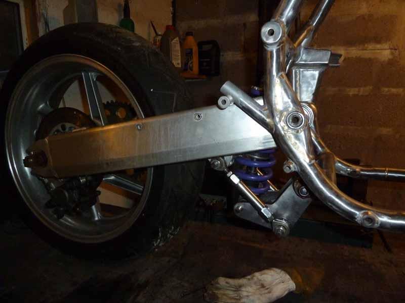
managed to adapt a swing arm to replace the bent Harris - keeps the same wheelbase. Made up a bellcrank to also replace the Harris item - also bent but i've done this to"fit" versus "tune" and it needs further tweaking to get the swing arm rake right. My thoughts were - make what fits as long as it isn't to far from original - get bum on seat feed back and use the Tony Foal suspension program to tune it right - However! project direction is starting to evolve in a new direction turns out there is someone reasonably close to where I stay that has a trident frame XR69 - I have a GSX1100 engine ( and a GSXR1100L) - you can see an obvious direction - the Suzuki floater suspension would be pritty easy to adapt to the mag3 to, i've changed too much of the frame already to call it a mag3 anymore so why not go the whole hog so i'll stop this project here and when I firm up on the above - i'll start again on the project page
-
great description. can you advise on the alloy grade you used and if there's a need for any post assembly heat treatment
-
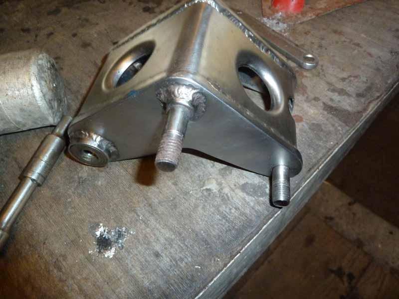
making the jig for me, there is only one key relationship to get right - get the steering head perpendicular to the swing arm axis - within limits all other aspects can be otherwise accommodated for ( and used ref: the existing frame geometry) 1st - set the support for the steering head - I used an existing yoke stem accurately fitted to an extension tube ( 100% parallel to the stem) and weld this to your base frame - vertical angle relative to the length axis is not important but make sure it is in the centre of your base frame and 100% 90deg perpendicular on the width axis 2nd I used an old set of bearings to lock the frame head stock into this stem (big note! - learned from not doing this!! - make sure you thoroughly degrease these bearings, if not - any welding work around the headstock will get contaminated by the grease via the heat / capillary action) - using your headstock bearing set nuts - clamp this down tight 3rd - now you'll find the position of the swing arm pivots - make the x 2 supports for this identical - i.e. don't match it to the frame - measure to only one side and make both sides from this - in this way you'll find out if the frame is twisted (i.e. it will not fit!!) -- initially when I did this I had to work the swing arm pivot in through the supports and frame, seemed like there was a bit of misalignment (twist)- about 1/8th" - ok there was enough flex to get it in but you can see - if i'd made it to fit the frame I would have been an 1/8th out 4th - then I started cutting out the damaged frame tube's ( RH side had the crush damage as can be seen - LH side looked like there was a slight buckle on the lower rail - quit a bit of spring when the tube separated i.e. there was a lot of tension in it - kept cutting away until I was left with just the two top rails connected to the headstock 5th - after cutting out - I removed the frame from the jig - and re installed it - hayho - the 1/8th error had gone - spindle fitted much easier now - ok confidence is good, no signs of need to initially straighten the frame if you look at the previous pics - you can see I chose to cut the main frame rails just fwd of the swing arm vertical part - my reckoning being, this is a relatively low stress / flex point being supported by the rear engine mounts on one side and fwd lower engine mounts on the other - I did bush this joint for added support - there's x 2 welds here - 1st was the bush to the tube ID (V notch) - then the top tube butt weld
-
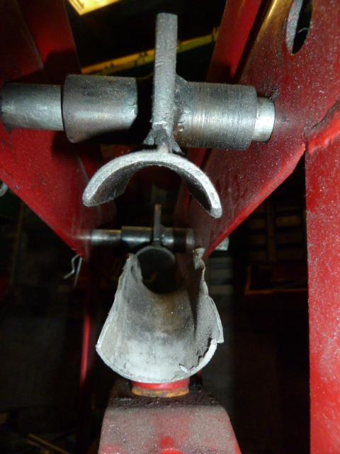
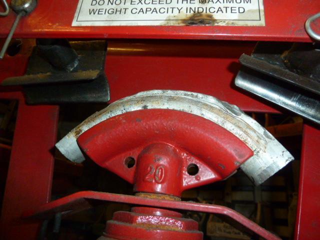
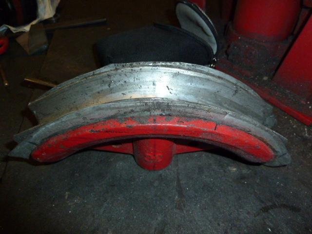
Bending the T45 Chrome moly tubing: armed with a 12T hydraulic press bender - about as cheap a tool as you can get for this job, my 1st attempt's were crap but after a bit of trial and error I was able to achieve successful bends, not perfect - there is a bit of flattening but using the original framework as a comparison reference = well good enough. I can't say if this is the best way to do it but it's what worked for me 1st - junk the roller supports that come with these benders and replace with saddle supports using some tube with an ID slightly larger than the OD of the pipe you want to bend for the saddles - doing this prevents the brooze mark's that the point loading of the roller supports creat 2nd - turn down a broom handle to make tube plugs and fill the pipe with fine builders sand - take your time doing this - tapping the pipe and packing the sand as tight as you can get it - then hammer in the 2nd end plug ( best over fill with sand - try fitting this plug - remove a bit of sand - repeat - you don't want to under fill 3rd - the trick is to make a bend former fit really tight to the tube OD. I 1st made inserts from various bits of steel tube fitted inside the selected former to bring the ID of the former close to matching the OD of the tube - easy done - cut pipe in half and use another bit of scrap that fits this ID to enable forming this insert into former using the bender. For the last insert, to match the tube OD - I used alloy tube, bit of fudge factor here, the ID of the alloy tube slightly smaller than the OD of the T45 i.e. enough to make a really tight fit and use the alloy's ability to flow into shape - don't initially form the alloy into the former, just lay it across the former with the T45 inside it and use the bender to 1st squeeze the T45 into this alloy sleeve, then you start bending both the T45 and this alloy sleeve together - I think whats happening is a) you get a tight fit and b) your spreading the bending force versus a point loading at the peak of the former 4th - work the pipe in small increments - take up the spring 1st, then just a few mm of bending - release and repeat - think a few hrs of this per bend to give you an idea of the small steps lubricate around all pressure points on the T45 to ease removal ( you'll have to chisel the alloy sleeve off) I couldn't get to a full 90deg bend doing this but not far from it and more than enough for the purpose of the frame - in the pics the final alloy sleeve is after bending the T45 - imagine it was was initially straight with the T45 laid across it OK so yi don't need an expensive pipe former - great if you do but it can be done with an e-bay special
-
will do
-
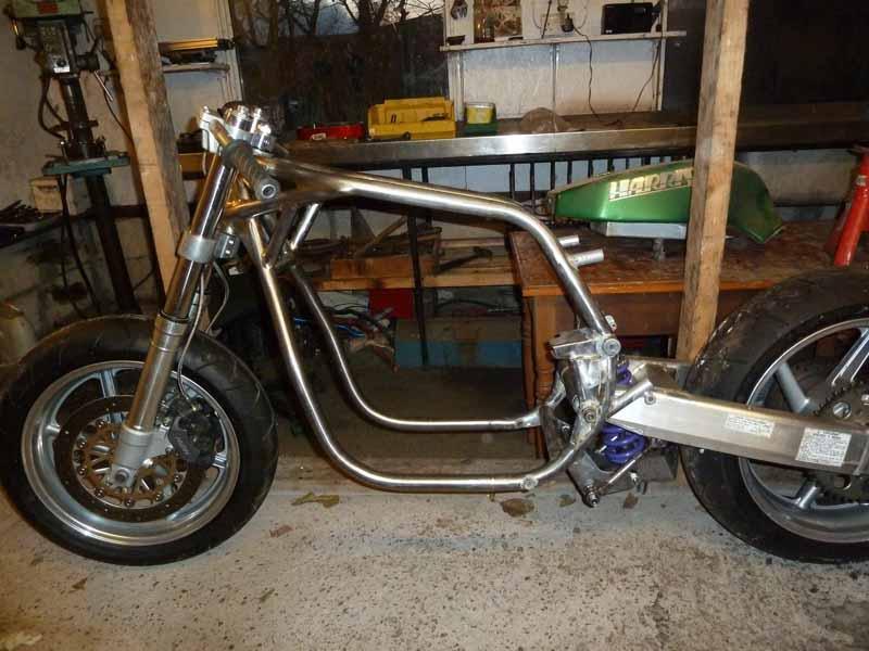
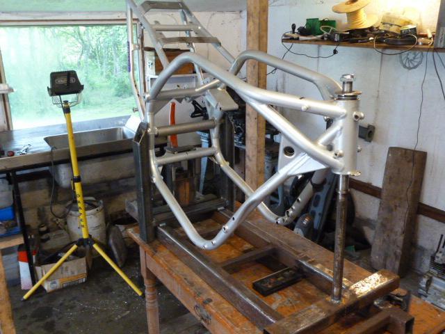
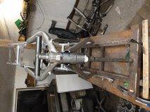
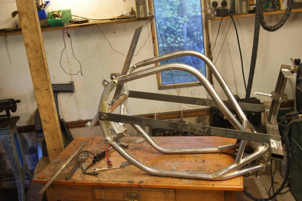
The Mag 3 suffered from a fair bit of impact damage - TBH could have been scrap so with nout to loose decided to see if I could learn to work with T45 chrome moly tubing and bronze weld. Decided on TIG bronze weld, so after a lot of practise with different techniques and filler rod spec - managed to work the T45 tube with a cheap e-bay special pipe bender and achieve reasonable welds using SIF albronze wire no. 32 - i'll go over what I learned doing this in more detail but suffice to say i'm reasonably happy with the end result - up to Harris std - nope - good enough to be safe ? - I'm confident - ok so I progressed with making a jig for the Harris to see how bent it was, surprised to find - even though there was significant tube damage - it appeared straight! - turned out it was the swing arm + bellcrank + rear suspension mounts that were bent - another "more detail" part that i'm presently attempting to sort - after repairing and modifying the main frame loops - I made up another jig to check for alignment and happy to say the head stock to swing arm relationship is straight and a fresh set of head stock bearings fitted i.e. no head stock deformation due to the work now done around it. I'm not finished the frame work yet - got the do the engine mounts and fit a low front cross beam - but i'm holding off until I get a GSX1100 engine to see if I can achieve a reasonable fit for both the Gurls blouse and the Suzuki engine around these parts ( the GSXR engine looks a better fit after modfying to fit the Gurls blouse engine than the original GPZ 1100 layout) so i already have a solution - but my heart is for an air cooled GSX 1st pic is the original Harris in the jig - you can see the main damage - I cut out all the original tubes except for the top rails and head stock and played around with various set ups until finalising on a layout that closely matches what Harris did in the 1st place - not because I specifically wanted it to be like it was - but simply because this was the best layout out - atleast to my way of seeing it. The last pic shows the jig for checking the post weld alignment - basically a lazer pen is attached to the tube extending out of the head stock - the two side rails hold the head stock accurately parallel to the swing arm pivots - the plate on the swing arm pivot is accurately perpendicular to the swing arm pivot, so! when you slide the lazer pen down the head stock tube - it projects onto the plate on the swing arm - if you get a parallel line from the lazer that matches a line scribed perpendicular to the swing arm pivot - on the plate, then its straight - it was !!! - not "almost - or close" it was like rail tracks - however it was offset by 2mm from what is the centreline between the swing arm frame rails - I can only surmise that this is how it was originally - no otherwise reason
-
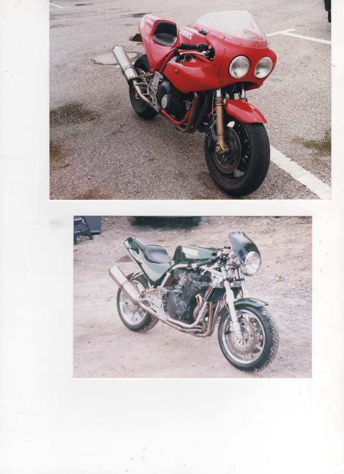
Hi - as per my intro I'd like to put my project build on here - and welcome all your good advise bit of history leading up to the project: I have a magnum 3 in a sorry state after a big crash and a classic Peckitt and Mcnab Gurls blouse from the formula one TT series (late 70's early 80s) in need of restoring to original "as raced" condition. I enjoy the journey that a project build takes you on - as much as the finished project Initial plans was to build two Gurls blouse CB900 based engines - one for each chassis - use the bent Harris as the mule / tinker and focus on the P&M as built restoration, however the cost of the Gurls blouse engine build is mounting - so I'm now looking at 1st repair and revise the Harris for the Gurls blouse - once sorted transfer the engine to the P&M and fit a GSX1100 or GSXR to the Harris = with an eye on an XR69 rep i.e. two of the great icon bikes from the TT series - that's now the present target I've been learning techniques and making progress with the Harris frame so I'll be able to show this progress up to where I am at - then things will slow down as we move to real time pics here are history of the both bikes - the Harris as I got it with a FI GPZ1100 - then adapted to GSXR; the P&M as when I got it (modified into a RS1000 endurance rep by the previous owner) and a picture of it when it was raced and what I intend restoring it to. It's got a great history - one of the two bikes P&M campaigned with a works RS1000 engine - a journalist for MC mechanics adapted it to the endurance rep. - some of you may recall an article on this bike back in feb 1985 in Mechanics "endurance specials on the road" featuring this bike and a tasty P&M Kawasaki KOOL rep - well this is how I acquired it