


nlovien
-
Posts
622 -
Joined
-
Last visited
Content Type
Profiles
Forums
Events
Everything posted by nlovien
-
maybe of interest to add something a bit different - http://www.classic-motorrad.de/classifieds/racing-teile/racing-teile-in-romeitaly-and-pragueczech-republic_i14081
-
so yir sticking with the 1100
-
mind, the alternative option of fitting a 750 may not provide the clearance it suggests - i'm not familiar with the detail but you could loose the height advantage via a different inlet port configuration - raised inlet roof / steeper downdraft angle - I believe this is already an issue when fitting the 750 dot heads to 1100's in some std frames
-
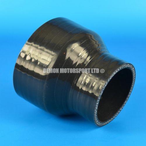
they are mega £ but more the idea, you've got the filter material ref: your existing foamies - going along the lines of markfoggy suggestion - add in another good post on this forum from a guy who has seen good dyno results ( better than K&N) with a really neat and cheap solution using hose expanders as velocity stacks, or you could use the std rubbers from an airbox - all yir needing is some glue - maybe a backing plate made from thin sheet or plastic to create the seal between the stacks and the foam you have basically adapt what you have to "sock" over some kind of stack http://www.Eblag.co.uk/itm/151315674845?_trksid=p2055119.m1438.l2649&var=450517287519&ssPageName=STRK%3AMEBIDX%3AIT
-
I use an ITG car filter on my KTM - works, if you go to "view base plates" on their web sight http://itgairfilters.com/category/megaflow/ you'll get the range of sizes - the sausage filter range will be better suited - good thing is you've got to make yir own base plate to mount to the carb so in your case you could then set the filter low relative to the carb inlet to better fit the frame how about x 4 of these - I have used them and they worked great - can't get much smaller for the given through bore
-
no - looked at it on my bike - hence why "wild idea" doesn't look practical, but when yir in the shit
-
wild idea - as you need the extra length to get the carbs into the rubbers, unbolt the rubbers from the block - fit to carb then see if you slide the whole assembly in
-
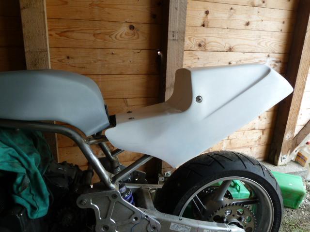
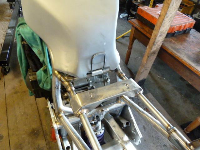
thanks - had to take it off the bench to go fix another bike, but before I did i've sorted a bit thats been bugging me - to trim the front of the seat in an attempt to get a shape that works - metal is easy - you can put back on what you take off but thin fibreglass - once its off, its off - not an exciting picture but it reflects a good few hrs with a bit of mental intoxication ( whisky ) - perfect - nope, happy yes whilst i'm otherwise focussed would be a good time to get it painted - can anybody advise on the right colours for the XR69 red/black and yellow ? - its the trident XR69 i'm using as a guide - thanks
-
the section on dynamic balance alludes to the reasons for a machine - my very basic understanding = static is fine but is limited to seeing the assembly as a whole - like your presuming all the mass is on one and the same vertical axis, but it isn't, its distrobuted along the horizontal axis of the crank - and the distance between say two mass's that statically balance induce's what is called the rocking couple and the further apart, the more this has an effect ( hence why static balance works better on a single versus a 4 cylinder ) - anyway, let a man of knowledge better explain it - can't attach the pdf but the link to it is https://www.google.co.uk/search?q=4+cylinder+crankshaft+balancing+principle&oq=4+cylinder+crankshaft+balancing+principle&aqs=chrome..69i57.12468j0j7&sourceid=chrome&ie=UTF-8 Dynamic balance. Figure 2a illustrates the concept of dynamic imbalance. The object shown is clearly in static balance, because the moments of the two masses balance each other about the spin axis as in figure 1a. The offset of the two masses along the spin axis gives rise to what is often known as a rocking couple. As such an object rotates, the orientation of this couple also rotates, attempting to move the axis in a conical manner. To achieve dynamic balance, we must rearrange the masses such that the rocking couple disappears. In practice, this is done by either removing material from the object, or sometimes by adding material. Figure 2b shows how the addition of two extra masses can achieve dynamic balance, which also guarantees that the object is statically balanced. The idea of the possible generation of a rocking couple is very important to the subject of engine balance. 2a. 2b. Fig. 2 a. Each of these two masses create centrifugal forces, and because of their separation along the axis or rotation these forces produce a rocking couple. b. The addition of two opposite but otherwise identical masses is one way to remove the couple and restore dynamic balance.
-
that is looking good, if you were to draw a line around the engine - especially from the front and around the bottom = thats where the frame is - thats neat
-
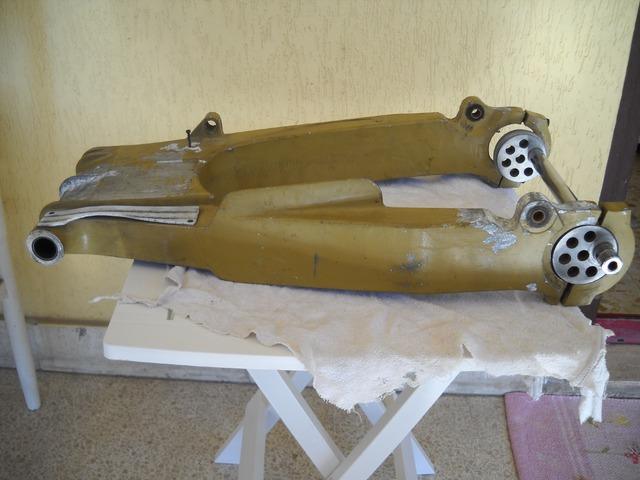
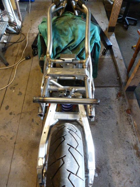
right that's the seat subframe tacked up - done the wrong way - free hand versus making a jig creating a rod for my back getting it all aligned but after a few bits of scrap bin manufacture i've got it close enough. The smaller OD top tubes are an ingenious technical development - saving aprox 20grams in weight - yea - bollocks, I ran out of the larger dia. chrome moly tube - hayho - it enabled sliding the seat support back and forth to aid locating the seat - right, next is all the tabs and mounts needed for mounting things - got to do a bit more seat shaping at the front - not sure yet how to finish this - the original Harris body work = the tank sat into the seat - hence why i've made a tank support and why the bottom of the tank looks like it needs to sit into something, going to live with the tank and seat being seen as two separate parts - i've also modified the swing arm = now getting the droop I was looking for
-
been a while for an update - have made a bit of progress - never as quick as you wish though, however I came up with a neat thing to solve a pain - getting the seat sitting square on - argh!!, tried x 3 times with the frame mount that picks up on the seat mount bobbins on the side behind the bum rest - you working blind to it when you fit the seat - just needs to be out by a few mm and the seat just isn't right - ok, so I left one side with the tapped bush on centre to pick up on the matching seat mount, on the other side I made a bush thats a nice sliding fit into the frame mount hollow tube, then I tapped this bush off centre at two different places ( to get two different cams from it) OK so 1st attach this bush with the off centre tapping to the seat, then you offer the seat up to the frame and let this bush socket into the frame tube - ok, then add your spacer to the other side and make up the mount to the centred tapping ( this will space the seat - horizontal @ 90deg to bike axis) as the other side bush can slide out of the frame tube as you tighten up the opposing side, now you just turn the allen bolt that mounts the sliding bush with the off centre tapping, because of this, as you turn the seat moves up and down and pivots left to right relative to the bike axis - find the sweet spot / mark up the bush relative to the frame tube - remove and weld in place - job done bollocks - next time - make a jig and do it properly
-
if the forks are "feeling good" but not travelling as far as desired = hydraulic/ spring versus mechanical - if they are feeling harsh "sticky" = mechanical - fork brace being a potential culprit - and IMO once we moved beyond the days of skinny flexible forks these things are more bling than value - the comment to deep sea them is a good one don't pay much attention to static tie wrap testing, as you say - they feel good - go stand her on her nose with the front brake to see where the tie wrap goes, but do check your air gap / oil level 1st or you'll pop the seals
-
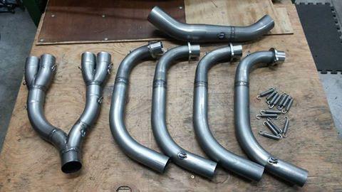
you'll get the big motor in buddy, maybe fit reduced ID ex stubs until you get past the first turn then flare up, jay gui do this - don't know the GSXR but the CB Gurls blouse guys get great performance from this pipe - forsure it costs a lot - thinking more to mod. an existing pipe - pic is for a Gurls blouse - GSXR uses same design
-
does it run better if you raise the idle ? - another one is you've balanced using the throttle slide adjusters - now go to the idle screws - maybe just a 1/4 turn on these could bring it back in " typical idle screw adjustment = turn one way listen for rpm rise or drop and splutter - turn the other way listen for same - where you get the highest rpm rise, set them at this position, then adjust idle via the main throttle adjuster"
-
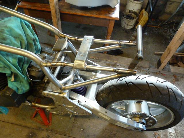
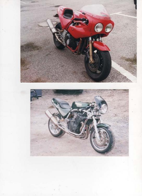
this was mine before I mangled it - ref: the green version when it was the Harris frame for the big fat GPZ block - note - I had room to turn and feed No1 and 4 ex header inside the frame downtube - although I bent the RH downtube, swing arm, bell crank pivots and seat rails - when I jigged her the headstock to swing arm pivot was true -- Harris built these things like the 4th rail bridge
-
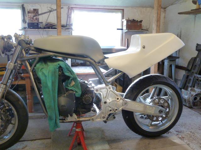
my original harris swinger is 530mm centre to centre +/- same as the CBR1000 arm i'm now using - I modified my frame to original fit a CB900 based motor - one of the longest out there, an air cooled GSX1100 does also now fit - my frame was originally built for a GPZ1100A1 - a big lump of a thing - so where's the difference ? take a close look at the triangulation bracket linking the bottom of the head stock to the frame down tubes - I think this F1 frame has the down tubes raked further back = pushing the engine further back - anyway, it looks like where the frame front down tubes drop from the headstock is where you can find room for a bigger engine - dependant on what harris originally built the frame for whats interesting is - it also looks like my sprocket location is further fwd - add in an extra 30mm on the swing arm length = two frames with a lot in common but the front/back weight bias will be quite different - add in, I'm using the big fat 130 profile 16" front from MrHonda fireblade V I think your using a 17" rim ? - going to be different handling bikes - buddy we'll have to meet up some day and compare
-
thats one you want to look at - we've all got our own tastes and i'm seeing lots of bits that float my boat - no bling, just the right combo of parts that make it work as a whole thing
-
your focus is on the means to get rid of the heat - I would check your oil filter and oil pressure to see if the relief valve is working - stuck open ? other focus is something has changed that creates heat - previous comment ref: blocked jet, or an air leak around the carb manifolds, or has the ignition timing gone out, or is there a blockage in the ex pipe - if you happen to be using adjustable cam sprockets - have they slipped
-
dam't near spot on the same - i,m 920mm if you drop a plumb line down +/- 930 axle to axle - yet i'm 140mm from the sprocket centre to the swing arm - your build looks like the sprocket is nearer to the swing arm. - I've read that Harris based the mag3 on their F1 chassis - atleast with this bit they obvious did many thanks
-
this is turning out quite neat - your managing to tick the box's whilst cramming the engine into a frame that's just about as tight as you could get for the engine - whats the wheel base ? I'd like to compare to my magnum 3 based project - to take out any swing arm length variation could you measure from swing arm pivot to the front axle - apreciated
-
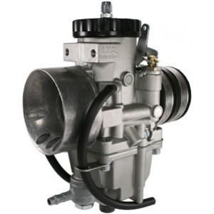
check where you have the pumper starting - if it starts as soon as throttle touched - try backing it off ( sounds like you might be pumping fuel in - avoid excessive throttle tweaking ) - also you could try a larger pilot air jet as an alternative to a smaller fuel jet - its the AFR your trying to get right , the idle screw on these is a "volume" adjuster versus an AFR adjuster
-
great post - i'm not familiar with the oil cooled gsxr engine - seen a good few of these external oil pipe feeds, been meaning to ask - got my answer here brill
-
2nd on the welder heat - I use a TIG torch - no added wire, just heat the bearing shell until you see signs of the metal flowing - I have also ground out a slot using a dremel - not cut all the way through - then hit the slot with the welder to pull the ends together - she'll drop out then
-
the principles are the same - key difference is in appreciating the difference between direct lift and CV with respect to how you imply the relative jet circuit operating range on direct lift - the 1/4 - 1/2 - 3/4 - full is directly related to throttle lift position = so you can mark the throttle lift in quarters to gauge this on CV - its more related to engine demand - I think of it as idle / light / medium / full on = so you got to be more focussed on how the engine actually responds to load demand during acceleration - marking the throttle isn't accurate another area ref: Cv not covered is in playing with how the CV throttle slide lifts - ref: the return spring and pressure balance holes but with the bst 36 - i've not found a reason to mess with this - std seems to work fine

