Bike of the Month September 2017

Goodbyes are never easy but they make for a good occasion to honour something or someone that has done OSS (very) proud. Let me fill you in…

Maxwin stumbled on the scene in January 2016 mid-development of his 750ET after having competed in the 2015 season of the Earlystocks championship. Having cobbled together the bike for 2015, the early days of 2016 were there to fine tune the bike and get it all working a bit better, looking a bit nicer and going a bit faster.

As with pretty much every build I’ve ever seen on OSS, thing spun a bit out of control with lots of clever engineering, pole positions and ultimately, big crashes. If you’re not crashing, you’re not racing. There’s no argument to say our friend Maxwin didn’t try his very best.

One of the very first to be promoted to OSS Winged Hammer, he has kept us up to date with all the ins and outs of the ET, plenty of pictures and YouTube videos for us to ogle over and wish for it to be us on the clipons and having a go ourselves.

Personally, I’d love to go racing, but lack of talent/balls/money will see me get my fix trying to hassle my bike around during rookie-level trackdays, dreaming of keeping up with the likes of Maxwin and his Earlystocks-compadres.

But, this is a goodbye, and for OSS an instance to honour someone who in turn honoured our request to fly the Winged Hammer flag and do his part for our little community. After a few heavy crashes, our friend choose to follow the path of progression (as you do with racing) and that progression sees the ET and Maxwin parting ways, with a water-cooled 600 of a not-to-be-named brand waiting in the wings to bring new highs in the career of our friend.

Update: It will be a Slabby 750 for next year, hurray! The ET will stay and progress, for Maxwin keeping it and let his dad have a go.

If you’re not crashing, you’re not racing. If you’re not trying to take things to another level, you’re not racing. If you’re not out to get that next second off your lap time, you’re not racing.

Maxwin chose racing and thus, we must say goodbye but not before we award him with the BOTM September 2017.

You sir, have truly done us all a big favour by letting us enjoy your updates and it makes me personally very proud to see our stickers on bikes used as intended and doing a bloody good job at it too! Thank you, I hope you return into our fold at some time in the future, for now, all the best 🙂

Congratulations on Bike Of The Month September 2017

Buildtread here

Turbo Kits and Performance Parts

loopy pic 1Fancy websites and a huge social media profile are all nice and dandy but the real recommendation for a craftsman’s work is in the examples you see, hear and touch and … if you’re really lucky maybe even experience. When it comes to the FastByMe HQ, there is no shortage of examples at varying stages of turbo-ness in build state, power and career path to get a good feel for what performance enhancement is right for you. The enthusiasm and downright bloody-mindedness that can’t see any reason why all motorbikes shouldn’t have one radiates from the King Pin of the operation Dave Dunlop who is supported by his ever patient wife, Samantha.

Tucked away in the now not-so-quiet confines of a sleepy Rutland village, Dave can be found slaving under the Fast By Me banner as he has done for many years. We’re not quite sure how many exactly, but the doctor’s note was issued before word processors. Long enough is a good answer.

Dave predominantly creates custom turbo solutions but extends his offerings to other performance parts including billet big blocks and cam oil feeds as well as a range of tshirts and hoodies to wear when you’re going really fast. For more information and a range of live action videos, check out the website www.fastbyme.co.uk


loopy pic 2

loopy pic 3


loopy pic 4

loopy pic 5Dave will be offering a 10% discount to OSS members for complete turbo kits so don’t forget to mention the site when asking for a quote.

As an official introduction on the site, Sam is offering a Fast By Me hooded sweatshirt to the person who can identify how many times FastFurby can be found on the website www.fastbyme.co.uk

Send your competition entry over to terriblethunderlizard@gmail.com – closing date 30th September – get counting!

Fitting a 916-style Steering Damper

By Banoffee.

My slabby has a lively front end, so I’ve been wanting to fit a steering damper for ages. I even acquired the period Daytona fitting kit and damper however couldn’t get that to work with my USD front end. So, seeing as I wasn’t keen on modifying the frame to take a bolt-on side mounted damper the only option left was a 916-style fitment. Seeing as I’m running an Ohlins rear shock, the damper had to be Ohlins to match of course!

Basic theory:
Whilst steering damper manufacturers don’t list fitting kits for oldskool bikes, it’s actually a simple matter of taking the measurements and then doing some research to find a suitable kit (or parts from several kits).

The measurements: (Note – some measurements are taken with internal vernier edges, some external. These are just shown to illustrate, you should of course check your own measurements carefully!)

A: Yoke nut centre to tank front mount centre

AB: Top of tank mount to top of top yoke

BC: Between centre of tank front mount bolts

CD: Between LH lock and centre (then multiplied by 2)

DThe research:
I took a tape measure with me to bike meets, bike shops etc to measure up more modern bikes (with owners permissions of course when they were about!) and also bothered a few people selling kits on ‘that auction site’.

My bike:
(750G with 400gk76a USD front end)
A: approx 50mm
B: approx 60mm
C: approx 50mm
D: approx 60mm

Things to note:
On my slabby, the damper is quite close (5-10mm) to the tank. Double, triple check all measurements to ensure it won’t foul anwwhere.
Source the fitting kit before buying a damper so that you can mock up and modify if necessary. Setting a good search on ‘that auction site’ makes this surprisingly easy and cost-effective.
For the damper stroke, obviously err on the side of slightly longer but not too long as it will look unbalanced.

The result:
I picked up a 2000-model H*nda Firebl*de Harris fitting kit from ‘that auction site’ for a whopping �20. Measurements were near-perfect as a 1-2mm on the tank mount, etc. is just fine. Only slight drawback was 30mm lower ‘B measurement’ so I acquired a 30mm tubular spacer.

EMy ‘D measurement’ (remember to multiply by 2 of course!) meant an approx 60mm stroke damper so I ordered a 63mm stroke Ohlins damper from BikeStuff (cheers Rich!).
In the pics below you can see the finished result. I’ve lost a tiny amount of right-lock, however, eventually I’ll get a spacer made up to under the tank-mount part which will solve that. All-in-all I’m well pleased!

245

Journey to the center of Mikuni’s BST38SS carbs

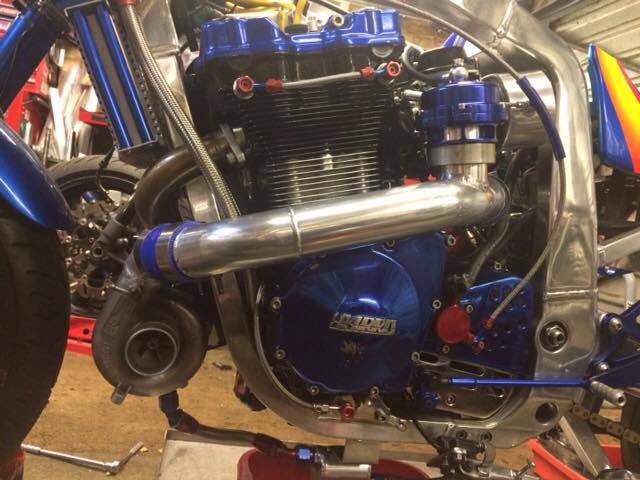
Journey to the center of Mikuni’s BST38SS carbs.

When I was studying my new 38mm slingshot carbs my eyes fell on the small rubber hose which runs along the outside of the carbs from the float chamber to somewhere above the intake. I disconnected the hose and started tracing the circuit inside the carb.I did this by reconnecting the hose to one of the fittings and bowing into it. So by hearing where the air escapes you know the routing of the circuit.bst38ss-1

The top fitting connects to the uppermost hole in the bellmouth, but when I blew into the fitting of the float chamber I seemed to have hit a dead end because there wasn’t any air escaping. I noticed a small plug which looked like a jet inside the float chamber. I removed it and now I could blow trough it. First I thought the jet had been clogged but after closer inspection it really was a plug instead of a jet. So there was a hole in the bellmouth that connected to the float chamber, but the hole was plugged. I had some sleepless nights trying to figure out what the function of this would be.bst38ss-2

Then I decided to do some investigation on the web. I didn’t expect to find much info on Mikuni carbs on the web, but suddenly I found this article deeply hidden inside Factory Pro’s website…


Power Jet Circuit, GSXR750, as installed on air cooled gsxr750 w/ 38mm Mikuni carbs, 90-92

Power jet carbs – Mikuni’s great addition to a carb used in a high rpm application.

The power jet adjusts high rpm mixture, in the gsxr750 – from 10 to redline, in 1/3rd the step of a main jet change. Changing a main jet, in the 38mm carb, as installed on the gsxr750, adds or subtracts up to 2% CO per main jet change – when the CO% needs to be adjusted in in .2%-.4% for best power attainment.
Changing the power jet allowed much finer increments of change and, just as critically, happened to change the fuel delivery curve to what was optimum for the gsxr750 – something that would have required main air jet changes and other modifications to attain, but would still leave the main jet fuel delivery steps too coarse.
Strange. This Powerjet circuit works wonderfully when tuned on the stock airboxed gsxr750 (and it’s pretty straightforward to tune on our EC997 Low Inertia Eddy Current dynamometers unlike simple inertia dynos.

The method of operation is as follows.
At full throttle, as the rpm increases, at exactly 10k, there is enough of a pressure differential between the float bowl and the airbox interior to draw fuel up the black hose on the LH side of the carb and exiting through the hole at the top of the bellmouth of the carb.
The fuel is metered by a jet that is located in the bottom of the float bowl. The jets are sized in increments of 2.5 or .025mm. Usual size for a gsxr750 with a stock airbox and air filter might be between #58 to #67.5.
The power jet circuit, when properly tuned, adds the equivalent of 2-3- main jet sizes “on top” of the main jet, so, if you were not using the power jet circuit, i.e. had a “0” or blanked jet installed with a #125 main jet, you would use a #117.5 with a #62.5 power jet installed.

Since this particular circuit works on the pressure difference between the float bowl and the airbox interior, it is absolutely affected by any change in the pressure differential. If the air filter is changed to less restrictive unit or the airbox inlet is modified, creating less restriction – the power jet area (size) should have to be increased above the usual size, though, a BMC or K&N, as installed for stock replacement, may only require 1-2 sizes increase in the power jet (in addition to +2-+3 on the main jet circuit).

If the airbox is removed, there is no longer a sufficient pressure differential to pull the fuel up the ~2.5″ vertical rise from the float bowl to the outlet in the bellmouth and the circuit is no longer effective.

Why is the Powerjet circuit difficult to tune on a simple inertia dyno and easy on our EC997 Low Inertia dynamometer? According to the former owner of Dynojet, the powerjet circuit simply doesn’t work because there is a lag in fuel delivery at 9.5k rpm – creating a flat spot there. It turns out that the reason that he saw that is that the dynojet dyno has insufficient load to simulate the Real World Loading ™ that is present on the bike in 4th and higher gears on the road or track. There is a slight delay in the onset of Powerjet fuel delivery, but it’s only vaguely present in second gear in the real world, and not present in higher gears due to the slower acceleration rate that occurs when you are actually riding. If you were racing, as Yoshimura USA and other non sponsored, large US Suzuki sponsored teams (we lent them carbs for the Finals) verified, the kit outperformed anything dynojet had to offer.

How to tune:
1. Install the main jet that produces the best power at full throttle / 8k-9k.
2. Install the powerjet set that produces the best power at full throttle / 10k to redline.
3. Raise or lower fuel level to get best power at full throttle / 3k.
4. Recheck main jet and needle height if you needed to lower the fuel appreciably.
5. Adjust fuel screws for best idle.
Note – this is the “short” tuning list!

Benefits:
The size of the main jet DOES affect the low and midrange. Excess leanness isn’t usually the problem on these carbs. Using a #117.5 vs. a #122.5 main jet (PJ equipped vs. using a #0 PJ ) leans and crispens the lowend and midrange for better off idle and corner exit performance.

There other applications on other motorcycles that use circuits that are called “power jet” circuits that work on different principles – some are electronically controlled and work in the midrange like RGV250, the RS250 for upper topend, where they activate and deactivate through different ranges and still others work for different reasons and by different principles.
“Power Jet” is a catchy sounding name and it gets used every few years or so…

Why did Suzuki specify that US and UK models, for example would have a blank or “0” jet installed, disabling the circuit and other countries, like Canada, got the activated power jet circuit (though with pretty odd settings)?
Emissions? I don’t think so. With the basic fuel level and needle settings virtually the same on both applications, using the larger main jet, as required with the circuit blanked, would only increase hydrocarbon emissions under measured conditions.

At any rate, the circuit works extremely well in dealing with the coarse main jet metering steps of the older style gsxr750 carbs – 1st through 5th place at the 1990 WERA Grand National Finals used our Factory Pro #CRB-S06-1.0 Carb Recalibration Kit. Pervasive kit use followed for the next couple of years -until 1992, the last year of the power jet.


Says it al really, but what I can’t figure out is why mine have size 0 jets fitted as my carbs came from the UK and so should have a functional circuit according to the article.
But anyway, as I am using separate K&N’s the powerjet circuit won’t be able to function properly so I removed the tubes and plugged the outlets inside the bellmouths.
This way you won’t have to disconnect the tube every time you want to change the main jets which can save you a lot of dyno time and therefore money. Now you only have two screws for the top cap and two for the float chamber which makes them very service friendly.

Thanks to Factory Pro for restoring my good night sleep!

Now that we are talking carburation technology I would like to point out two other things that are important.

When I remove the airbox and fitted separate K&N’s there were a few hose fittings that I didn’t know what to do with.bst38ss-4 In the middle of the bank of carbs there’s a 14mm big hole which acts as a breather for the float chambers. You need to connect a hose to this which is about 30 centimeters long to

A.) prevent dirt from entering the float chambers, maybe you’d even fit a small filter to the other and of the hose. A good and cheap trick is to nick some of your girlfriend’s nylons, put a piece of it at the end of the hose and keep it in place with a tie-rap.
B.) create a kind of buffer for the air pressure below the diaphragms. This is very important for the same reason you need to add tubes to the fittings of the float chamber breathers.

You need to connect a tube about 20 centimeters long to the fittings bst38ss-3of the float chamber breathers which are located between carbs 1&2 and 3&4. If you don’t do that the air pressure inside the float chambers will become very perceptive to pressure changes outside the carb like when you get some sudden sidewind or pass a big lorry.
I didn’t believe this at first until a dyno operator did a run before- and after fitting the hoses. The hoses made the powercurve much smoother and therefore made it easier to choose the right jetting.

Marc Salvisberg from Factory Pro Tuning says;

In the US, with a stock airbox, we didn’t have ANY problems with crosswinds, even 40-50mph gusting crosswinds at full lean at 100mph boogie. Actually, there is one problem – getting broadsided with a 50mph gust WILL push you off the track! Willow Springs in southern California. I thing that the biggest problem was the carb tuning as rides with our carburetion setups could: run with or without float bowl tubes, tuck their knee in of out, draft to the inside or outside of another rider while in a strong crosswind! It’s been a few years, but I definitely do remember the lack of problems with crosswinds. Urban myths started by someone in the States! Do the hoses affect the carburetion? Perhaps, to a very small effect. Less than running the bike again and increasing the crankcase temp 10F!

The only thing I can say is that we did a run with- and without the tubes installed and the effect was very clearly visible on the dyno graph. So when you fit separate K&N filters be sure to fit those hoses for the horses!

Thanks to Sandro Serafini, creator of Evo2 for the delicious carbs.

Piston-deck height

Deck height is defined as the distance between the top edge of the piston crown (with the piston at TDC) to the edge of the cylinder liner. The closer the edge of the piston crown is to the edge of the cylinder the high the compression ratio will be.

So if you have pistons that are 10.5:1 and they are 0.010″ below the edge of the cylinder and you are able to reduce the deck height by 0.010″ then the actual compression ratio of the cylinder will be increased.

The reduction of the piston deck height can be accomplished in several ways. Machining the cylinder block is the most common method.

A word of caution you must know exactly the minimum valve to piston clearance that is required. this varies in different engine designs. To increase the piston to valve clearance usually the valve relief pockets on the piston’s crown are enlarged or the height of the piston at TDC must be lowered in the cylinder.

Oversize Valves

Some tuners believe that larger size valves enhance Hi-RPM power at the expense of Low-RPM power. This has proven to be false due to the results of dyno tests and theory. Larger valves enhance Hi and Low RPM.

When a valve is closed it has no size whatsoever for a cylinder’s ability to induce air flow. A valve that is opened, 0.015”, appears to the cylinder as a small valve. Only when the valve reaches 25% of its total lift point does the cylinder actually experience anything near the true size of the valve. If a cylinder was stuffed with valves as big as possible to create a greater movement of the air/ fuel mixture and exhaust gasses and the larger valves proved to be excessive (too large), the solution of the problem would be to reduce the valve’s lift, besides reducing the air flow it would also reduce the wear and friction on the valve train. In the real world, the criterias for the intake and exhaust system for making peak HP and torque at a given engine RPM is the cross section area of the intake and exhaust ports, not the size of the valves.

The real advantage of using oversize valves is that, for a specific rate of the valve’s opening, an oversize valve will give a greater breathing area to the cylinder quicker. This is equal to as a smaller valve opened at higher rate of acceleration. Any time there is a higher acceleration rate in the valve train, more stress is created.

As long as valve shrouding is not a factor then the largest possible valve in a cylinder head will allow the engine to develop power over the widest RPM range, not just increase the flow at high lift rate. If a dyno test of a engine with a cylinder head that has oversize valves reveals a loss in low RPM power it is because the engines camshaft has to much overlap.

For carbureted normally aspirated Suzuki engines in the 9.5 to 12:1 compression ratio range the exhaust flow needs to be 75 percent of the intake flow. Overall when the compression ratio of an engine increases, in order to obtain the maximum results an exhaust valve can be made smaller in relation to the intake valve. This is due to the power developing earlier in the expansion cycle of a cylinder in high-compression engine, thus allowing the exhaust valve to be opened sooner and longer without any problems. A small exhaust valve will create the opportunity to use a larger intake valve.

Longer exhaust duration

Most stock camshafts from production 4 cylinder engines manufactured today are ground with the longer exhaust lobe duration,or that they are ground with shorter intake durations. This can be viewed that either the Exhaust Ports or Exhaust Pipe system is somewhat restrictive, and needs assistance, or that the intake system is very efficient and cam timing can be trimmed back without a sacrifice in power, in order to maximize throttle response and cruising efficiency. There is no absolute correct viewpoint in a stock engine running at conservative RPM levels, for the sake of overall efficiency, fuel economy and a quiet smooth running engine, this staggering of intake and exhaust duration is quite common and appropriate.

High Performance is another thing entirely. Change one factor, such as the exhaust system installing headers and larger pipes and the need for that longer exhaust lobe has been eliminated. Now add to this change a different carb system and camshaft and you have really changed the equation. But, why is it that so many racers & cam grinders insist on running a cam with longer exhaust duration regardless of what equipment is used? The answer is habit, many have been somewhat successful in doing it this way and will never change unless forced by circumstances.

The best result comes when we realize that an engine is basically an air pump. Air is pumped in and out and there are problems when one side or the other is restricted. Balance and flow is our objective, unless you are NOT trying to make more horsepower!

Most experienced Tuners run a single pattern cam, equal on intake and exhaust duration. This type of designed cam always make more torque.

Logbooks

THE LOG BOOK:

I have 2 Log Books, the first one is for the engine and the second one is for the bike.

ENGINE LOG BOOK:
Contained in this Log is every measurement or weight of components that are subjected to wear, this includes the transmission, clutch plates, clutch springs, crankshaft, connecting rods, pistons, piston pins, piston rings, camshafts, valve guides, valve stems and valve springs, drive chain and sprockets . Although you may consider this time consuming the benefits are substantial. Once you have a baseline of your measurements then the next time you disassemble your engine you will have a very good picture of the wear rate of all the components. This process will virtually eliminate parts breaking from fatigue and you will be able to determine what aftermarket parts are more durable. For example I know using a certain type of piston ring in my 1327cc EFE race engine that for every 165 passes down the race track that both my top and second ring end gap wears 0.001″ of any inch. This was the same wear rate that I encountered with my 1230cc EFE race engine using the same type of piston rings. So I know that the oil that I am using is working and the quality of the part is consistant no matter what the power out put is and that after x ammount of passes I have to replace the rings before the power starts to drop. Utilizing this measurement process for the last 20 years I have found that the one part of the GS /EFE engine’s that wear out the fastest are the valve springs, and by the way I have never broken a valve spring in over 7,100 passes down the track.

RACE BIKE LOG BOOK:
In this log I list my tune-up ( jets, timming, drive sprocket size, tire psi,), in additon to the brand of race fuel and octane, my launch and shift RPM for the particular track that I am racing at. Also before I unload my bike, I list measurement of the temperture, humidity, wind direction including approximate speed, and air density and record the time of day. I remeasure and list all of the above items every hour that I am at the track. The info gained from these measurements is very beneficial when you are racing a dial-in type of class, because it makes the tune decission for every round easier. Also once you collect all of the above info you will have an insight on your bikes performance the next time you race at the same track if the weather and time of day is very close.

Intake & Exhaust Port Surface Finish

As long as the intake port surface finish is fine enough so that the highest protrusions are not above the air /fuel mixture boundary layer thickness, then improvements on the finish will have little effect on air / fuel mixture flow . A rougher finish is actually an advantage. Do not over polish an intake port because of its wet fuel flow capability.

A polished exhaust port will increase the exhaust gas flow and will reduce the potential for carbon to build up on the exhaust port surface.

In conclusion 97% of a performance gain from porting a cylinder head is from the shape of the ports and only 3% is from a polished finish.