Compression ratio

When you increase the compression of an engine it will produce an increase in the HP and Torque output throughout an engine RPM range. If a long duration cam is installed in the engine, increasing the compression ratio at the same time has a greater advantage than these two modifications made separately at different times. By raising the compression ratio of an engine, the peak combustion pressures are increased.

Engineering studies have found that cylinder pressures are about 100 times what the compression ratio is. That means that an engine that has 10:1 compression ratio, would create 1,000 psi of peak combustion pressure. Increasing the compression ratio will increase an engines cylinder pressure and this increase in compression also increases the an engine’s thermal efficiency. Thermal efficiency is a measurement of how effectively the an engine converts heat into mechanical power.

Due to the fact that a high compression cylinder makes its power much earlier on in the power stroke there is another issue that can be taking an advantage of. That is that the early opening of the exhaust valve opening needed for high RPM output can be utilized without effecting the engine’s low RPM output.

How much HP and Torque can be gained from an increase in an engine compression ratio?

By using the chart below you can fiqure the thermal efficiency at any given compression ratio. First locate the original compression ratio listed horizontally, then locate the new compression in the first column. Where the two compression ratios intersect, that is the gain that can be expected. For instance if the compression ratio of an engine is raised from 9:1 to 12:1 the two values intersect at the box with 7.7 in it. This is the percentage increase of thermal efficiency that can be obtained from raising the compression from 9:1 to 12:1.

ORIGNIAL COMPRESSION RATIO New Compression Ratio
9:1 10:1 11:1 12:1 13:1 14:1 15:1

10:1 2.9
11:1 5.5 2.5
12:1 7.7 4.7 2.1
13:1 9.7 6.6 4.0 1.9
14:1 11.5 8.3 5.7 3.5 1.6
15:1 13.0 9.8 7.1 4.9 3.0 1.4
16:1 14.5 11.3 8.6 6.4 4.4 2.8 1.4

Comp ratio

On normally aspirated engines at low engine rpm’s there is little ramming from intake charge velocity into the engine’s cylinder. When the piston starts to move up in the cylinder bore on the compression stroke prior to the intake closing, some of the air / fuel mixture is pushed back into the cylinder head’s intake port. This creates the situation were the volumetric efficiency and the effective displacement of the cylinder is well below 100 percent.

Raising the compression ratio one point from a low ratio has a greater effect then raising the compression ratio up from an already high ratio. This means the larger the duration and lift of a camshaft the more responsive it is to a increase in the compression ratio, especially in the lower engine rpm.

Camshaft lobe centres

Here is some info that might be helpful for those who are interested in fine tuning their bikes camshafts.

The common range of lobe center values for SUZUKI engines is only about 10 degrees wide from about 102 to 112 degrees, a change of one degree can have considerable effect on the power delivery characteristics of a SUZUKI engine.

The effect of moving lobe centers is that by advancing the intake and retarding the exhaust, known as CLOSING UP THE CENTERS, it will increase the valve overlap and will move the power UP in the RPM range, although it will at the sacrifice LOW- RPM power. The result would be LOWER numerical values on both intake and exhaust lobe centers.

If you retard the intake and advance the exhaust, known as SPREADING THE CENTERS, valve overlap will decrease and will result in a WIDER power band while sacrificing HI – RPM power. This is indicated by HIGHER numerical values on both intake and exhaust lobe centers.If you move only one cam the results are not as predictable, traditionaly it is the INTAKE CAM that is moved to change power characteristics since small changes here seem to have a greater effect.

Air density, a secret tuning factor

Air density is a computation mainly dependent on the temperature, barometric pressure, and the humidity of a volume of air.

Temperature in the USA is generally measured in degrees Fahrenheit, barometric pressure in inches of Mercury (inHg), and humidity in percent of Relative Humidity.

You can relate to how these factors effect the density of the atmosphere by using a balloon to simulate the earth’s atmosphere. When a balloon is filled with air and placed into a refrigerator it begins to shrink, this is due to the drop in temperature of the air inside the balloon. As the air cools it releases energy and slows down,because the air molecules are not bouncing off each other as much, they remain closer together and more of them will now fit in a smaller area. The opposite will occur if the balloon is heated.

The effect of humidity is a little more complicated. A change of humidity in the atmosphere is caused by a change in the amount of water vapor mixed in with the common gases already present in the air. As more water vapor is put into the air is displaces these gases. The water vapor is also less dense (weights less) than the gases in the air. When we take air that is at a set temperature and pressure and start introducing increased amounts of humidity we begin to cause the overall density of the air to decrease. Therefore, the density of the air is the greatest when there is no humidity.

Changes in temperature, pressure, and humidity can have different amounts of effect on the associated change in air density. A change in temperature or pressure causes a proportional change in density. In other words, a 1% change in temperature causes a 1% change in density. Again, the effect of humidity is more complicated, because the effect of humidity on density is also dependent on the temperature. A 50% increase of humidity when the air temperature is 70f degrees may cause a 1% decrease in total air density, but a 50% increase of humidify when the air temperature is 90f degrees may cause a 2% decrease in total air density. This effect is due to the fact that it takes lot more water to cause 50% relative humidity at a 90 degree temperature than it does at 70f degrees. The humidity must also be considered in that it makes up some of the density of the air, but it has no value being there.

The air in the earth’s atmosphere is made of various gases and water vapor. Neglecting the effect of pollution there normally is 20.9% of oxygen, 75% of Nitrogen, Carbon and very small amounts of some other gases. Oxygen is the most important gas in the atmosphere as far as an internal combustion engine is concerned. This is due to the fact that the oxygen is used to burn the fuel placed in the chambers of the engine. When more oxygen can be placed in the chamber it allows one to also place more fuel along with it and therefore create more power. The air density relates to this because when the air density increases the amount of the combined gases and water now fit into a smaller area, this includes oxygen. If the air is denser than there is more of it therefore more amount of oxygen will be taken into the engine.

The term commonly heard among racers is “density altitude”. Density altitude is the density expressed if feet instead of grams per cubic centimeter. It’s a lot easier to relate a change of density in a couple hundred feet rather than a change of 2.534 g/cm^3. The use of density altitude is taken from the U.S. standard atmosphere table. This table relates the density of an average day at sea level (59 degrees, 29.92 inHg) and how it changes at different elevations in the atmosphere. As one climbs in altitude the density falls off at a predetermined exponential rate.

In conclusion I highly recommend either an Air Density Gauge or a Altimeter as tools to be used for adjusting your Fuel Curve and Ignition Timing. I firmly believe that these items are essential for tuning at the Race Track

Oldskool Oldskool, the road less travelled

614982_10151073061812733_377962059_oJohn Oliver (AKA Yoshi-Johnny, AKA YJ) is a long time OSS member and Pops Yoshimura enthusiast. John is a professional bike mechanic and many will remember his iconic take on the classic Wes Cooley GS 1000. Ten years ago, when John first rolled up at an OSS gathering on his GS, for me and many others,  at the time, his bike fully embodied the true  spirit of OSS. An air-cooled 8 valve GS1000 engine and classic Wes Cooley paint job but running on modern 17″ wheels,  sporting a mono shock conversion  and a set of gold anodised upside down GSXR forks. Evolution of the species. John’s love for Suzuki’s 8 valved air-cooled GS1000 engine has never faded. We asked John to tell us a little about his dream engine build and here is what he told us.

KM

Oldskool Oldskool, the road less travelled. John Oliver

It’s always been a dream to own a full blown Yoshimura motor but I don’t earn enough to just go out and buy one so I am gonna have to do it the only way I know how, a p.p.p.piece from here and a p.p.p.p.iece from there. So, I am in the process of getting together for the race bike I am going to prep for myself to go racing instead of others!

Engine

Yoshi motor
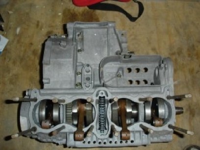
I got hold of an old NCK drag motor a few years ago and it has a pretty good crank and gearbox in it. Crank has Katana rods and along with being welded it has straight cut primary drive gear, along with a matched one for the clutch basket. Cases have been lightened and dipped at Ribble Technologies in Preston. So the bottom end is as good as my budget will allow for the moment. I do need a new clutch before it turns a wheel in anger and this will involve having the straight cut fitted.  Originally the NCK engine was a 1420 drag engine but on the road or track that sort of capacity would generate too much heat and quickly cook itself.

yoshi pistonsGraeme Crosby in conversation said he preferred the power and reliability of the 998cc motor as it gave enough power and was reliable, Pops and he discovered the bigger the capacity went up, the less reliable and problematic it all became. Craig Smith, my good mate in Australia who has been on here for years is a major inspiration for the build as his black “skunk” race bike is still one of the outstanding bikes on the site. He raced it to good effect in NZ and didn’t suffer with reliability issues. He went bigger and bust his crank!His motor punted out 135 rwhp and that is my aim with this… I won’t be gutted if it doesn’t get there, but it would be nice if it’s something like.

So the pistons are custom made 1100cc Wisecos and are one of only 3 sets made this particular profile I think. All the gaskets and seals will be replaced with standard (where necessary) or Cometic (where it’s ok to cheat!) and special ones (base and head).

Head

bladeThe cam chain was a weak spot on Yoshimuras race engines and the team did all sorts to try and reduce the extreme wear during races, extra jockey wheels, longer cam chain, shorter tensioner blade, POLISHED cam chain links and manual tensioner were all employed in the hunt for reliability. Most of this development actually went into the first GSXR engine. So all the above mods will be done to this engine.I have had a jockey wheel and plate made but Roger Upperton does a better version which is more like the GSXR version than the one I have. The extra jockey wheel at the back of tthe head is the reason the tensioner blade is shortened.


Yoshi headThe head has been checked over and overhauled from scratch. Bigger valves, seats cut to match and a tidy port job will make the gas go in quick and hopefully make it work right.

camsValvesCams are very lumpy custom profile ones from New Zealand and require cut aways for them to turn in the head! Shims will be under bucket care of Kibblewhite, buckets, retainers (titanium) and collars. Dialled in cams will be easier with Rogers version of the jockey wheel than the Smithy version. I may put a twin plug set up in as well when I actually get to the build

Carbs
Carbs will be Mikuni VM33s and are getting quite scarce, these are about as big as you should be going on a bored out GS1000 engine, anything bigger just makes them bog down when you crack the throttle open.

Jockey wheel


Ignition
Ignition will be taken care of by Boyer Brandsen mini digital set up until I get a self generating system organized…

Speed is all a question of money…I wanna go fast but my wallet says whoaaah.

YJ

Discuss here

Tuning your Kat – the basics

A standard Kat is nice as standard, and a valuable classic as is, but it’s very hard to resist the temptation of modifying it. You can hardly find one that hasn’t been tweaked to the max. In my point of view for a Kat to remain a Kat you have to retain the standard fairing, tank and frame. So here are some of the options…

Engine tuning

Well, what can we say about tuning GSX1100 engines other than the sky is the limit? Thanks to the immense popularity with drag-racers you can build an entire engine completely from aftermarket stuff.
It has to be said that the drag bike guys have been moving more and more towards the GSX-R/Bandit engines purely because the supply of fresh engines is becoming more scarce. The most popular tuning method for a GSX1100 engine is the big-bore kit in combination with a top-end overhaul including a headflow, hotter cams and maybe bigger valves. A good excuse for taking such action is when the engine starts burning oil after churning away lots of miles. Anyway, you could go on and on about the options and still only cover 50% so I won’t go with that.
Many people are opting to fit an 1127 (GSX-R) engine, which is a dead shame for people who love the old GSX1100 engine, but a very good alternative if you’re after a low-mileage and reliable power plant.

Chassis tuning

Front end

From Suzuki’s point of view a headstock is just two bearings holding a steering stem (won’t argue with that 😉 and so they felt little need to change it’s design and dimensions during the last few decades.

That means that about any Suzuki front-end will fit the Katana… you’re free to interchange the front-ends of Bandits, GSX-R’s, Katana’s and GSX’s from about every capacity class, and even a CBR600 front end mixes in. Just remember to swap the whole front end incl. yokes and it’ll be a very straightforward swap. Keep in mind you’ll possibly lose some ground clearance after fitting smaller 17″ wheels and somewhat shorter forks.

Rear end

The space between the frame rails is 240mm. You need 30mm for the (25mm) chain to run free between the frame and the tire and 30mm on the other side to keep the wheel centered. So your maximum tire width = 240 – 30 – 30 = 180mm
To get there you need to move the sprocket outwards using an offset sprocket and maybe a spacer or two.
People who want to go wider than 180, like dragracers, need to widen the frame at the swingarm pivot and fit an outrigger bearing to the driveshaft (to keep the bending forces in control).
The hub will probably also need modification to bring the chainwheel closer to the inside.