


Gixer1460
-
Posts
5,538 -
Joined
-
Last visited
Content Type
Profiles
Forums
Events
Posts posted by Gixer1460
-
-
Your wiring is a mess!

The thick red and thick black are the only things that should be connected to the battery as std. - everything else is bogus! The problem will be that additions look to be all in black! Everything will need tracing / corrected / replaced as required. On a different matter - throw the exhaust away as it won't help the running, neither will those individual K&N's unless the carbs have been modified to suit - but with the bike looking as it does, I severely doubt it has! I foresee some power washing, lots of strip down, broken / snapped bolts, lots of parts but a serviceable bike at the end.
Don't bother with a magnet - IT IS a steel frame! The bit that usually rusts is the LH lower frame rail internally - water collects here if bike is parked mainly on a sidestand!
-
8 row cooler seems pretty small for a main cooler on an oil boiler - aftermarket coolers would be 16 or 19 row usually IMO?
-
Without seeing the two different cranks side by side, I would guess that the hyvo type would be slightly stronger around the sprocket due to shallower teeth compared to the deeper tooth profile of a roller chain tooth profile? I don't recall any reports of the hyvo chain being weaker through normal use - obviously heavier poundage valve springs and increased lift cams may add more stress on the chain / sprockets which could require just more maintenance observation? A 9k red line should be well within the chain's capability for 'normal' life. Certainly a stroked crank will help in that respect - mine is a +5mm stroke but done from billet and not a forging that has been welded and i've set my max @ 10.5k.
Sounds like an interesting project so i'll watch for developments.
-
On 1/25/2020 at 2:41 PM, Reinhoud said:
1100 rods are 1.5mm longer than 1000 rods, 78mm on a 1000 crank will give you 1238cc, 78mm on a 1100 crank will give you 1260cc
No one mentioned 1100 crank! So as I said, 78mm bore is 78mm bore and capacity only changes via stroke - not rods!
-
 1
1
-
-
1 hour ago, Brizznasty said:
Use the gs1100 rods on the 1000 crank there 18mm wrist pin then the 78mm gpz pistons. Really good combo about 1260cc.
On 1/2/2020 at 6:49 PM, kiwi said:Plus should of said it all comes out as 1238cc on 78mm bore

So which is it? Using longer or shorter rods won't make any difference with capacity unless the crank is stroked / de - stroked !
-
Look stock to me - no evidence of grinding and port not matched to rubbers. Valve guides are acceptably short which is good.
-
3 hours ago, BigT said:
The only magnetic piece in the motor should be the magnet on the oil drain plug
I think the OP means its steel ie. attracted to a magnet!
-
4 hours ago, gsx-f__k_UH13 said:
I'm trying to get TB's close as possible to make more room for plenum and TB's are 40mm.
Can't see you gaining (loosing width between individual TB's) as you'll still need adjustment mechanisms between so sounds like a lot of aggro for no big gain seeing as the plenum isn't exactly 'off the shelf' anyway?
-
Query - why make 'custom' boots if GSXR 40mm boots are available? If to accommodate bigger TB's, I would hope you've done a LOT of headwork on a B12 casting as it's not the best flowing example in the family - that prize goes to the GSXR1100 'M & N' variants which also used the 40mm carbs! Personally I have 46mm bore TB's tapered and fitted to 40mm rubbers, an 'M' head, ported, valves and cams to suit . . . . . . the turbo helps as well!
-
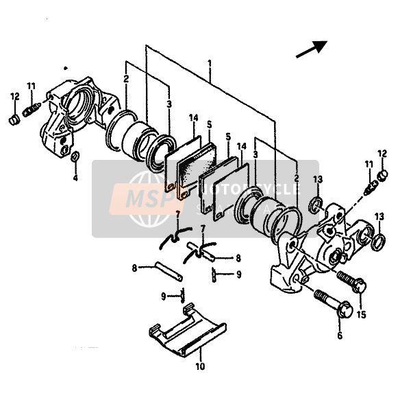
4 hours ago, Captain Chaos said:
The #14 pieces that the previous poster was alluding to are 'anti rattle / anti squeal shims. Whether you fit them or not doesn't make any difference that I can tell ! The boots look correctly fitted - you're not trying to use aftermarket discs or pads that could be fractionally thicker ?
-
1
-
-
You may not find any screws missing - its easier to replace one than go opening up an oil tight engine to retrieve a dropped one!
-
2
-
-
13 hours ago, wraith said:
The gaskets are rubber, so yes can be reused.
Provided you don't - nick em, rip em, or lose them!
They can go hard and do split / break on disassembly and are also prone to being flattened due to age and so leak on reassembly.
-
10 hours ago, Bobby said:
it was fairly tight squeeze getting the pistons in when on the bench, never mind trying to do it with the pistons on the conrod, that’s why I thought the first option.
will let you guys know how I get on. Thanks for the adviceNot really - The barrels will slip over the crowns of the pistons equally as they are all held level and still with the wood strips and the sleeves sit on the rings. You then go round the top rings, one piston at a time with a thin screwdriver, compressing the ring into the sleeve using gravity to slip down over the ring - start one edge and work along until all top rings are in. then start again from piston 1 - don't push anything, the barrel's weight is sufficient. Good luck trying to hold 8No buttons in place whilst holding barrels and trying to slide pistons into the sleeves!
-
8 hours ago, no class said:
....pistons on the rods , 4 wood shims to keep the 4 pistons level ,ring compressor , lightly oil , place cylinder block on the pistons , gently tap the block until all 4 pistons have cleared the rings .....
Is probably the best way!
Your described way is likely to displace a circlip into the crankcase and when you've retrieved it, you'll ping another off! It can be done but it's so much of a faff to be worth it! Oh and in any case, two sets of hands are useful!
-
This would confirm the 4No short studs
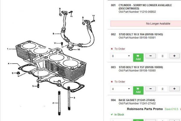
I'm guessing the 4No short ones are for the oil ways as they aren't defined? I'd maybe use your shorter studs in the centre oil ways although 4 matching would be better. Using long studs in short positions can't hurt unless you bottom out the threads before full torque is achieved.
-
Not if its aircooled ! Or a 750 ! Need all the info for confident advice.
-
20 minutes ago, Duckndive said:
Dooooh must try harder

LOL's - a 'senior moment' - comes to us all !
I would guess that due to the stroke difference of 1mm there would be a block difference also - that being said the drain tubes aren't exactly a precise machined piece and have considerable 'slack' for movement within the block and head .............................. so are probably the same part !
-
No more - no less reliable. . . . . just down to materials, where they are made and QA checking! OEM will generally be best overall.
-
Gregg
in Air Cooled
My comment was a generalisation but it was partially said .........
QuoteThe generator unfortunately (which has 2 wires connecting to the rectifier and 1 to the RH starter switch)
The actual starter circuit ie. ign. sw. / starter button / starter solenoid shouldn't draw more than a few amps, whilst the heavy cable between battery / solenoid / starter motor carries over 100+ amps. Poor starter performance often due to loose connections / poor earths, but a clean out of a 40 year old motor isn't bad advice either!
-
Gregg
in Air Cooled
Eh? The wires from the RR shouldn't go anywhere near the starter motor / relay or switch! 3 yellow wires from genny direct to RR inputs. Output wires from RR - black to earth / chassis ground and red to battery! Original Suzuki wiring has a RR output wire to the light switch which is acknowledged as a really daft idea leading to poor lights and charging and defective RR's. Duff brand new batteries aren't unknown either - a good battery should spin a motor over for at least a minute! Hopefully you have a decent RR and not one of the chinese rip off one's from Eblag!
-
On a paddock, oil loss should be minimal - there will be some but it ain't gonna flood out. Any common thin o ring which is approx the right dia or smaller can be stretched over will seal as its not under any pressure.
-
1 hour ago, davecara said:
I’ve been looking at dead head systems where the pump is controlled by a pwm(?) controller via the ecu. The pump is sped up as the fuel pressure drops, works well in a lot of yank stuff I’ve seen, I think it’s a bit too much for my little micrsquirt though!
looks very much like I’ll be going 1:1 rising rate reg between the pump and railThe PWM controller may work if the fuel demand / use is fairly linear - boosted engines are anything but linear! For the sake of adding a return fitting into the pump mount flange, a boost referenced FPR on the end of the fuel rail really is the simplest and most reliable system that just works!
-
1
-
-
I don't think they carry massive power at all so a 1/4 or 1/2w should be plenty?
-
1
-
-
Agreed - you can't mix and match pickups / plates / CDI's unless from the same model bike / engine.
-
1
-

gsx1100 oil cooler lines
in Air Cooled
Posted
Is the engine a GSX1100 or a GSX1100 EFE? The former didn't have an oil cooler, the latter did - although considering the size of them, what good they did is debatable! The oil filter cover on the EFE's is different to allow for the oil unions and divert the oil through the cooler.