slingy1157
-
Posts
223 -
Joined
-
Last visited
Content Type
Profiles
Forums
Events
Everything posted by slingy1157
-
Yes. Found this txt so i could see it in context. And it relates to a single coil distributor based system. As such you dont need a reference for the each spark event such as a missing tooth, just how many spark events required in the 720 deg of an engine cycle. The single coil then sparks this amount of times and sends the spark to the distributor (which obviously is referenced normally off the cam) to send to the correct cylinder. So in our application a 2 tooth wheel wont work. The minimum in theory would be a 4-1. But i think there will still be starting issues But to crisp up starting timing the backing plate could be slotted to allow the vr sensor to be rotated to put about 8 deg permanent advance into the system as cranking advance . Each coil could then be triggered on seeing the tooth rather than trying to calculate the advance off a very large fluctuating timing gap in between teeth. Hopefully the missing tooth would be obvious enough for the ecu to work out the 2 tach events. As soon as it catches and fires it should run ok in theory i suppose. I have a spare oem wheel. i might check it out in the interest of science lol
-
Cam sync is a necessity for any sequential running but can still be used for a batch fire wasted spark setup for better reference. I still aggree that its a complication not needed for wasted spark. Car engines generally crank alot more evenly on the starter and so generate more even tooth signals durring cranking but by all means please try it, and post your findings back here. There is alot more experimentation and variations to come from efi
-
I think it is because, the teeth create the sign wave as they pass the sensor but the gaps between create the pattern. So if you remove the large tooth you end up with 3 small teeth spaced 90 deg apart and 3 lage gaps, 2 the same size, roughly 90 degrees and one twice the size at 180 degrees. I'm sure it would run ok like this but the issue will be sarting to get it running! Because the cranking speed varies durring each revolution so much, (Just look at the varying line widths in my composite log above) each gap will take a different amount of time to pass the sensor resulting in 3 different sign wave events with no clear "This is the gap"moment. I think the oem large tooth leading edge would be used for cranking timing to eliminate this issue. So you could do it, or you could even grind the large tooth down to a matching small tooth to make a 4 tooth wheel, keeping the TDC mark on that tooth but either way it would need a cam sensor to create a crank reference point for starting which you can do with microsquirt as well, though it wont do sequential still. But it seems a PITA to fit a cam sensor compared to making a 24-1 or 36-1 wheel. Could be worth a crack by someone though. Anyone tried a GSX1400 Trigger wheel? Do they fit an oil cooled crank?
-
Fixed it
-
Sorry peeps, cant get the all the BL@*Dy pcitures to show. Help from an adult required please
-
Hi, managed to put this in the wrong section, can one of the mods move into the Turbo/EFI setup section please.
-
So i thought it was about time we got some hard data down on components of an EFI system. The biggest problem seems to be trigger wheels. I am just going to present what i did with as much detail as possible to try and give others an easier time of it. This is all based around my experience doing an install of the older (no longer available) Microsquirt V2 which had inbuilt high current drivers NOT the currently available Microsquirt V3, but all we are looking at here is the actual wheel and connections so shouldn't be too dissimilar and please, anyone else with experience of working 36-1 wheels on V3's feel free to add your findings to this as well. Microsquirt V2 Microsquirt V3 so you can source the 51mm trigger wheel needed from here. http://trigger-wheels.com/store/contents/en-uk/p7.html The suzuki wheel is 50mm so you will need to reduce the diameter slightly but that comes later. So before we take the oem wheel and 36-1 wheel and fit them together we need to make sure we can keep alighnment of where we want TDC to be on the finnished wheel. There are 2 ways to do this: The simplest way is to scribe the TDC mark on the OEM wheel in towards the centre of the wheel as far as possible. Then on the 36-1 wheel, with the missing tooth at 12 O'clock, count back anticlock to tooth 9, scribe a lign from the leading edge of this tooth to the centre of the wheel. Then when the two machined sections are pushed together, simply keep the marks aligned as near as possble. This will then be your new TDC mark. Or, the way that i did it was to make a jig that the oem wheel fitted on with a marker @ TDC. Then after i pressed the 2 pieces together, as near as possible, i then put it back on the jig and marked on the TDC on the new wheel.pictures below. So, once you've worked this out get the oem wheel machined down as close to the center section that goes in the crank as you feel practical, then machine out the center of the 36-1 wheel to make it an interference fit onto the oem center, then push together to form your new wheel while using your prefered alignment method from above. Mine was a good tight fit so i didnt wled it or anything. No problems so far with it but up to you. So, if you offer up the wheel to the engine now it wont quite fit, as its slightly to large. So at this point i started turning the teeth down and rechecking etc until i just had clearance to the VR sensor. This also does the job of finally truing up the wheel. I have 0.15mm clearance between the wheel and the sensor It should look like this Ok wiring,heres a picture of the OEM Vr sensor i am using from my origional 1988 GSXR750 slingshot. So this VR sensor has been on the 750 with a low comp 813cc kit in it, a 1052cc motor with 1mm decom plate and a stcok B12 engine, all have different cranking speeds and patterns but it has worked fine on them all. So, different Vr sensors may have different colours etc, im not sure so i thought i would do this so you can see what goes where and make adjustments to suit your wiring to match. I have yellow nearest the engine and blue on the outside. This relates to the my Microsquirt V2 as follows. Yellow = VRIN1+ (centre of coax) Blue = VRIN- (screen of coax) I beleive the V3 dosnt use coax but a shielded 2 wire set up but the wire names are the same and have the same inputs. I also used a mini timer connector (like male and female injector plugs) for this connection as i felt they offered a good weatherproof connection. Setting in Tunerstudio are as below and using ms2extra code 3.3.1 Now, if you power up your microsquirt and crank the engine, even with nothing else connected to the ecu you should be able to open the Diagnostic and High Speed Loggers in Tunerstudio and see the wheel being logged and it should look similar to below. It looks very messy in the tooth logger but in the composite log, you can clearly see the wide gap of the missing tooth every 35 bars. But heres an example of the Tooth Logger while the engine is idling. Very clean stable signal compared to above. In doing this i have found some documentation that the VRIN circuitry was changed between the V2 that i have and the V3 that most people are currently working with. My V2 basically grounds the sheild of the caox (VRIN- is permantly grounded essentially) and feeds the AC sign wave into VRIN1+ where as the V3 has a propper 2 wire scheme hence the change from a caox to a shielded 2 wire cable in the loom. But this means i think any issues with the VR sensors or wiring leaking to ground causes more problems. See TXT below Second, on the previous MicroSquirt® controller's VR sensor interface, the circuit was ground-referenced, meaning that the return path from the VR sensor is at 0 volts potential (or ground level). With the new interface circuit on MicroSquirt® V3, the VR- input has a weak pull-up voltage applied at 2.5 volts thru an internal resistor connected to the differential amp on the MAX992x (see the figure above). Also, the MAX992x comparator (+) input has 2.5 volts as well - this voltage will automatically adjust depending on the current adaptive mode but is centered around 2.5V. So, it is important to connect both VR sensor wires to the VR+ and VR- input. Also, make sure that there is no internal connection of the VR sensor to ground - use a multimeter in resistance measurement mode to make sure. The majority of VR sensor signals are floating and do not connect to ground. I wonder if the oem VR sensors are not well insulated to ground or something which is causing the problems that some are having with the V3's? Anyway, thats about it from me, hope this little lot helps someone out.
-
Aggree with 1460. The top end oil supply is controlled by jets in the block at the base of the studs that carry the oil anyway, so the reduced flow caused by the larger studs makes no difference as still slot more flow around the studs than the jets can deliver. The only thing i noticed is that the oil seals that go in the head gasket area are a tighter fit around the studs but again they only need clearance to match the area of the jet hole. So should be fine.
-
Havnt used it much be honest but seems ok so far
-
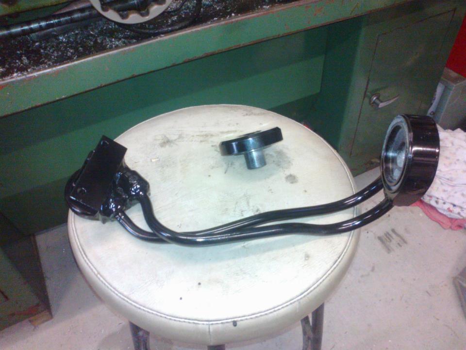
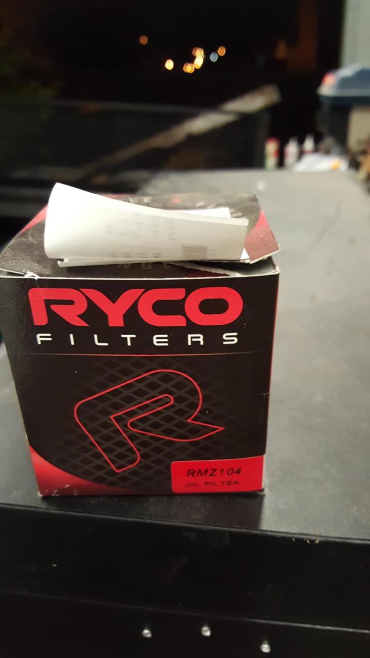
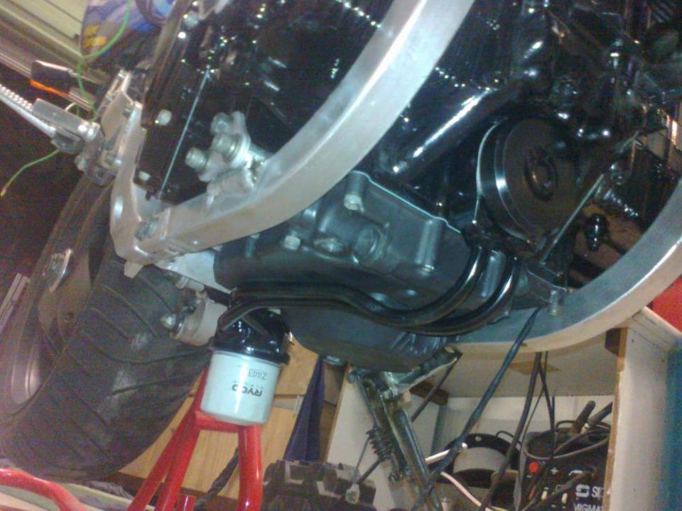
I think the RMZ104 is about 55mm deep OA so its pretty short. Heres a picture of my old remote set up i no longer need. Built to fit a 1052 motor, but would not work on the bandit 12 because the oil lines were in the way. Its still about 50mm deep i think. Filter looks low but was no lower than exhaust when it was on the bike. its a bit parallax errory lol. just an example of what can be done.

-
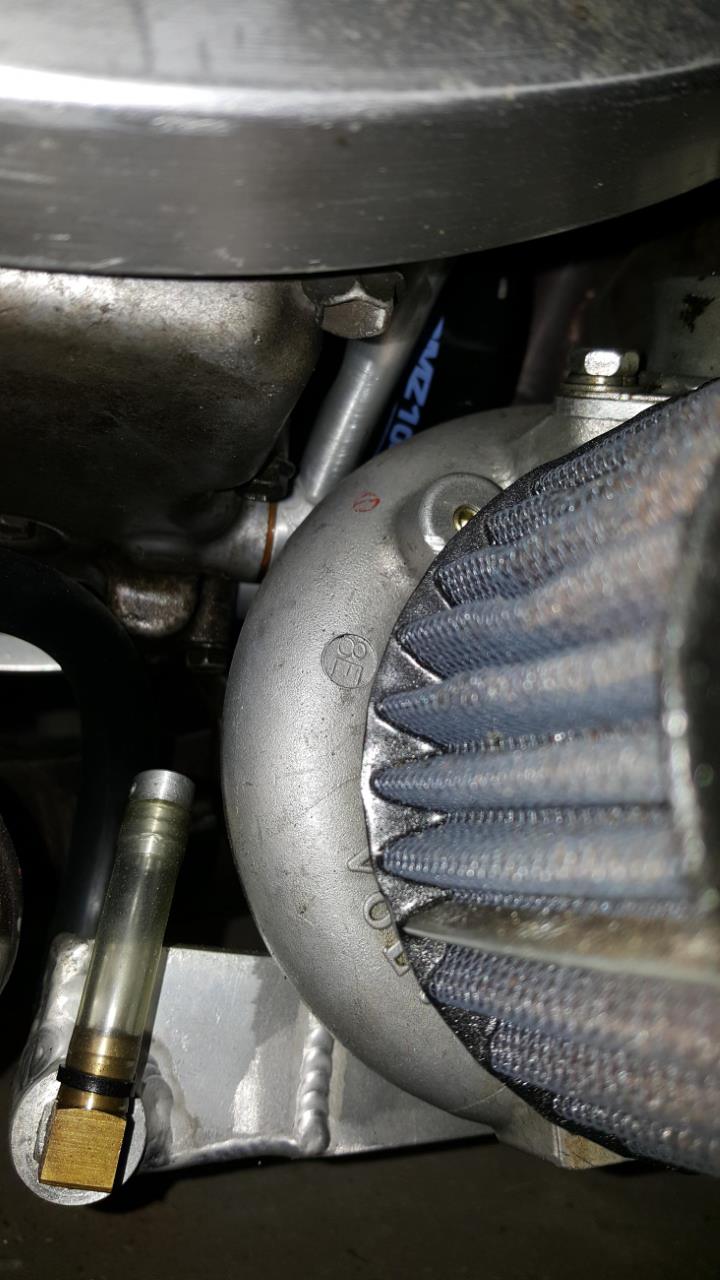
Yeah, i went through endless filter catalogues comparing sizes and fitment and this is the shortest filter that i could find, but it is an M20x1.5 thread as stated. Its pretty lost in mine but can just see it haha.

-
You can but suzuki use a unique m20x1 filter thread. I just so happen to have a sandwich plated with a cover made up with a m20x1 thread to suit with solid oil lines and a filter mount to move the filter under the shock. PM if intersted. Oh just noticed you dont have the filter thread anyway. The threaded hole on the block is some imperial size from memory as i made a new one to take an m20x1.5 super short filter for mine .
-
Pull the wiring plug off one and measure with a multimeter on ohms across the 2 pins on the injector. 1.7 - 3 ohms = low impedance Up around 14 ohms = high impedance. Have you followed the setup guide in the megamanual to get the software settings right. Won't matter what wires go where if the software isnt configured right. Megatune or Tunerstudio?
-
No takers. I am guessing they are a detuned gsxr600 based motor. And as such should just need spacing in the middle to suit, so the fact they are cast in 2 pairs bolted together in the middle should still be alright for respacing onto an oil cooled motor. They are SO much cheaper to get hold of than the K1 to K3 TB's. Anyone know what diameter they are?
-
Anyone know the centre to centre measurements of GSX650F throttle bodies? Cheers
-
What does the manual say for where the T aligns for tdc. Would probably be the same point used to set the cam timingtiming as well. T pointing to centre of left pick up coil maybe?
-
Yep, did it to get the IC in above it and its no lower than the lowest part of the exhaust, just looks real bad when the exhaust is off. FPITA! Next time, if there is a next time, a log manifold it will be with gravity drain, like i had on the 750. Keep it simple people, keep it simple! haha.
-
OOhh..Nice . Bet that was fun Ok cross the bandit idea off the list. Personally, having done the 1100 into a GSXR750 frame thing, i would never do it again. looks a bit better ,with the frame being a tighter fit around the engine, but the whole not being able to get the cam cover off in the frame and general lack of room under the tank is a PITA imoa. Stick with 1100 frames. What about the old oil boiler in a 1100 water cooled frame . I think they are the best looking gsxr frame, already have the bolt on subframe and heaps of room between the wheel and engine for what ever headers (or turbo) combo you could wish for. Just a bit more fettling to fit the engine buts its done quite a few times .
-
Yep, lap it. I had an old 100cc 4 stroke single once, had the same with the flywheel snapping the key, then undoing the nut and spinning off. Tried all sorts of things. Spot welds-Broke almost instantly, fully welded nut to crank- broke after a minute, steel bar welded across flywheel to crank- 2 minutes. After all this, the thread was fucked on the crank, so i cut it off and welded a piece of HT bolt on, i got some weld on the taper, so filed it back , then lapped the flywheel on to regain the taper and.................sorted, just bolted on to standard tension and never came off again. I would like to point out i was about 16 when all this bodgery went on and had a 9" angle grinder,a mig welder and BFH in the farm workshop as my main weapons of choice for fixing stuff and no real clue lol.
-
Original System, Turbo Shortstroke GSXR 750 running a IHI RHB5 turbo off a Fiat Uno. Microsquirt V2 ECU with internal ignition drivers GPZ1100 34mm TB's and TPS (direct fit on GSXR) 550cc Mazda RX7 Denso high impedance injectors (Direct fit into the TB's) Home made fuel rail to suit above Pierburg external pump SARD adjsutable FPR Copy GM 3bar MAP sensor GM coolant sensor GPZ750 turbo IAT sensor and plenum Ford EDIS 4 post coil 50mm 36-1 Triggerwheels,com crank wheel with stock pickup on stock plate. Innovate wide band sensor wired into ECU System runs batch injection and wasted spark so no need for cam sensor for sequential. Initally run with Speed Density (MAP ) Load control, then upgraded firmware to Extracode, which allowed the change to Apha-N with MAP Multiplication for load control. Speed Density for Ignition load control. All road and kitchen table tuned. It ran great but not great power. NA dyno was 81hp and 40ftlbs' on the carbs. Dyno below on about 10psi i think
-
Depends entirely what features you want? No use paying for a host of fancy features if you dont need them List all the features you really want to have it able to do, then look for an ecu that fits the bill for the money you want to spend. Like sequential, its great but in reality, makes little difference to anything for the amount of extra work and dyno time to fine tune. The only reason i would sequential is for the spark so you can go COP's and get the full 2 crank rotations of coil charge time, BUT, the fact that bikes, and Carby turbo bikes have been running the old wasted spark without issue for decades, makes me doudt if even that is worth it really. COPS are worth it though even if running wasted spark control so if one plug shits itself it dosnt effect the paired cylinder like a normal dual saprk coil would. I would still vote microsquirt but thats what i'm used to, does everything + a few extras and is cheap and compact. The software in Tunerstudio is excellant! You can configure everything yourself, update firmware, calibrate any sensors you want to use or just use listed sensors provided in menus . And the Alpha-n with multiply MAP function (fuel table uses TPS with MAP sensor reading calculated on top to come up with the injector pulse) works perfect for turbobikes. Others hate them, they can be temperamental, (just see the issues Danm54 had) but its nearly always because the settings are wrong, or the wrong firmware has been used or something the user has done to it. But its always the ECU's fault lol. Anyway, what ever suits your needs i suppose, theres lots of good ecu's out there know to choose from.
-
Depends entirely on what look you want and how much work you want to do to fit the engine? Any oil cooled gsxr will be pretty easy and look nice. Or if you like the OSS air cooled look they arnt too hard to put into any frame from a gs550 up to 1100's. So take your pick. They do fit nice in a gs550 frame without the gaps at the back or header issues. Or what about Bandits? Do you get the 600/750 bandits out there. So what look do you want?
-
Very nice, and efi too. Double nice
-
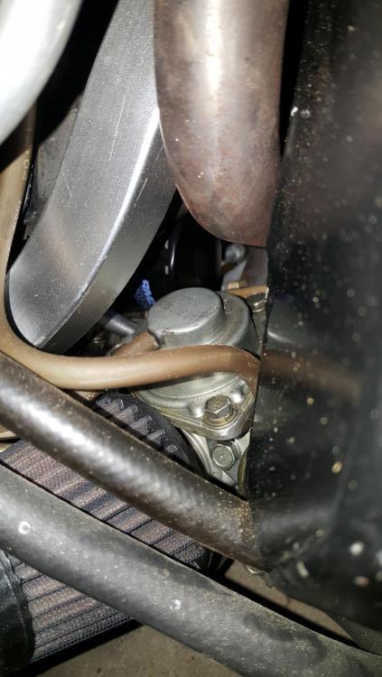
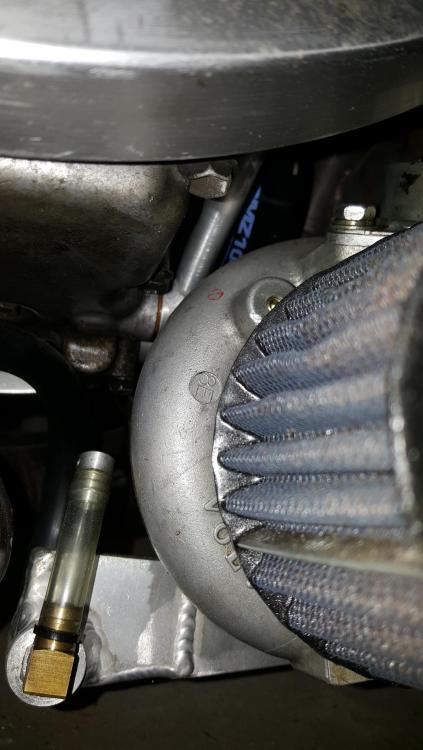
This my current setup. Notice the site tube so i can monitor the standing level of oil in the sump in relation to the turbo bearings, also, the alloy bung in the site tube has a small air hole facing the rear, which A. allows the oil to go up the pipe, and B.acts as a safety overflow, so if the oil does end up that high while parked, it can drip out of this rather than fill my housing.
-
Cool, scavenge pumps are my nemesis also, so will be interested to see your outcomes. i use a VDO pump which i got second hand for a good price as new they are pretty expensive, but it is very quiet and compact, but always looking for alternatives.