

slingy1157
-
Posts
223 -
Joined
-
Last visited
Content Type
Profiles
Forums
Events
Everything posted by slingy1157
-
Cant. I use an edis coil with a 3 pin polarised connector so cant swap my low tension wiring without cutting and I'm not doing that just for a quick experiment.
-
Thinking about it my plug leads are long enough that i could just swap 1-4 and 2-3 around and try the 4-1 wheel one last time on the above settings and see if there are any differences maybe. Will see if i get time.
-
Just had one last idea for an improvement with using the cut down oem 4-1 wheel though i havnt tested it but think it would help. So basically rather than using the 3rd tooth after the gap which is tdc for No1 cylinder for the reference for the first ignition event, use the 1st tooth after the gap. This means in Tunerstudio, the setting for "Tooth #1Angle (deg BTDC)", which was 180 deg in the video can now be 0.0 . This combined with slotting the vr backing plate to put 8 deg of stattic timing in for starting so our cranking timing in TS can also be set at 0.0 means that there should be minimal timing errors as we are now telling the ecu to fire on the first tooth after the gap. But we are now also telling the ecu to fire its first ignition output "ign1" on the first tooth which would normally be for cylinders 1-4, but this will now be for cylinders 2-3 as we are using the tooth exactly opposite the oem tdc for cylinder 1 markings know for our timing. So list this set up; 1. Remove oem wheel and cut off long tooth 2. Remove oem crank pickup backplate and mark and slot holes for 8 deg static advance. 3. Re install backplate and wheel. 4. Connect "ign1" output to driver for coils 2-3, and "ign2" output to driver for coils 1-4 5. Set Tunerstudio up as Missing tooth wheel No of teeth = 4 Missing teeth= 1 Tooth #1 angle =0.0 Cranking advance =0.0 6. Create an ignition table but minus your permanent advance from it. ie if you want 15* at idle put 7* in the table as you have 8* static dialled in on the back plate. So i think the above will be as accurate as the oem wheel can get, and would sure be an easy install. Would love to here from someone if they do try the above out.
-

Turbo charged with a roller bearing crank
slingy1157 replied to Reinhoud's topic in Forced Induction
Use an Aerocharger turbo. They dont need any oil supply as they have a built in oil bath that they run on so they can be mounted anywhere. -
Turbo charged with a roller bearing crank
slingy1157 replied to Reinhoud's topic in Forced Induction
I think generally its a case of over driving the normal oil pump by means of different ratio drive gears off the back of the clutch basket. Either gsx750 oil pump gears or propper turbo bike oil pump gears are available which spin it even faster. As its already got the reduction from the clutch basket its still no where near crank speed. Then place restrictors in the gallerys somewhere to bump the pressure up between the pump and the restrictors for use to feed the turbo. I'm sure someone will be along in the minute with better details. Could you build a feed and scavange pump into the end of a crank cover, like the geny cover so its more swappable between motors? Or like i think i mentioned in another thread, a belly pan type oil tank for the turbo so the lower oil level enables gravity drain with just an engine driven pressure pump (something internally regulated would be good) which pulls oil from this belly tank? Then engine can be left a bit more how oem intended. Any way love the look of what youve done there and obviosly proven to be a good system and with maggotbreath, would love to see more pictures on your set up.Would a hunt for cases similar to you last set save major rework? -
Man you are a real trooper with this. You had those issues with the ms which can be a real tedious head fuck and kill heaps of hours to troubleshoot. So you bite the bullet and pay for a "professional" install and tune but you seem to be right back in the thick of trouble shooting efi problems which seem to be mostly setup and tune related. I really feel for you. But, on the plus side. There is nothing like nutting out and understanding all the systems on your bike and you will be the Typhoon ECU Jedi master when done lol. Always enjoy following your updates as they are a shared learning curve for us all. Keep at it mate, your having lots of little victories here even if it may not feel like at times.
-
Are the coolant sensors for the ecu and clocks in different locations on the engine so giving different readings? To some degree it dosnt matter that the ecu temp values dont match the engine temp in real life. They are just numbers on a screen to represent values used in the control algorithms. The fact you know the discrepancy exists means it can just be allowed for. Ie if you want warm up enrichment to finish at 70 deg C then set it to finnish at 90 deg c if thats what the ecu thinks is 70. Have you taken the sensor out of the engine and put it in like ice water, then boiling water while watching on the laptop to see if it is actually reading nere 0 and nere 100 deg C? This should be as nere a real representative as you can achieve in a controlled manor
-
I tried to turbo my gs850 trike 18 yrs ago and had the idea to build a belly pan which held the oil for the turbo, thus giving a lower oil level and making it possible to still get gravity drain even with a lowish mounted turbo. Then only a pressure pump to lubricate the turbo driven off the engine ( or even electric as they are pretty good now and would facilitate pre and post oiling) with a dedicated cooler and filter would be required. But in the end i got a set of gsx1100 turbobike oil pump gears (even higher ratio than the traditional gsx750 oil pump gear swap) and found they fitted the 850 ok so i just went that route which seemed to work ok. And was able to keep the turbo high enough for gravity drain. Will be very intetested to see your pump solutions.
-
Awesome looking bike . Any more pictures Heinhoud? And what turbo did you use and what did you do to the oil system to raise the pressure enough to work with the turbo?
-
Monoshock using the gsx rear? or just fit the wheel and do an oldskool style underbrace on the gs arm with some piggyback style rear shocks?
-
I made an alloy block to replace the fuel tap with an alloy return pipe about 10mm in diam welded in that goes to just nearly touching the top of the tank. The end was then cut at 45 deg facing back to not spray fuel toeards the filler. This alloy block was then drilled and tapped on each side to take mini ball valves as fuel taps. Just a cork type gasket was used to seal the block to the tank. Works well
-
F#@k Yeah. That was easy. I did try to find a GSX1100G motor for my trike at the time but couldn't find one, then the GS1000g motor turned up so settled for that. Going to be an interesting build for sure.
-
I had a gs850gt trike which i put a gs1000g motor in. The 4 bolt drive flange was bigger on the 1000 but the splines were the same so just swapped to suit. The starter , alternator and cover all swapped over from the 850 as well. Then i used the 850 CV carbs on the 1000 by cutting the rack in the middle and welding in a little bit. Then stage 3 dynojet kit and k&n's had it running strong again. Couldn't believe the difference in power and torque between the 1000 and the 850. Massive gain. Dont know about going the other way. I like the idea of an oil cooled gsx1100g motor in an aircooled frame. Reckon that would look wicked and go hard.
-
You dont need a 600rpm column. Mine starts at 800rpm but as Danm54's table already has it, its easier to just leave it there. You would have to change every column value which dosnt seem worth the effort. It dosnt hurt to have some scaling outside of the normall operating parameters of an engine
-
Yep, thats how i did mine. Stud to battery or starter solenoid battery side. Then black yellow to ignition
-
Oh and i don't think 70*C is too hot. Most automotive thermostats are rated to only start opening at that kind of temp, and coolant dosn't boil untill over 100*c so plenty of margin there. I wouldn't remove the thermostat either! one of the functions of the thermostat is to slow the flow of coolant enough that it has enough time in the rad to loose the heat. If you remove it, the flow is so fast it dosn't have a chance to dissipate the heat in the rad and goes back into the motor too hot, hence the overheating continues. I would just monitor for the minute, and maybe start formulating plans for a bigger rad or something if you are concerned.
-
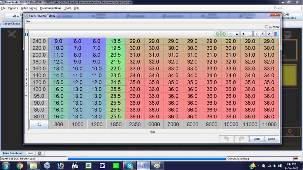
Does Guy Martin know you have his Tune file lol? The lower rpm, lower tps areas of the table are quite low in advance compared to where they should be i think. As bikes generally have a 2D style RPM based ignition map it seems quite complicated for no gain and it seems REALLY wierd to have the advance TPS referenced as well? Cant see this having any real relationship to engine load so is very ambiguous in what it can do. You have the manifold pressure compensation which looks ok so all the main table needs to be is an RPM based 2D table (like the OEM) as the manifold pressure compensation will add the 3rd dimension on a calculated basis rather than just a look up table. All the advance should be in by about 2500rpm as well. Here's a copy of my current table which i did originally for my 1052cc based motor which has all the timing in by 2350rpm according to the manual and it is RPM/Manifiold pressure based. So for all values up to 100kpa or NA running are the same for each rpm column, but then start to retard above this point as the boost comes in. You can also see that at the lower end of the table i raise the timing a bit so if the engine stumbles or drops revs there is a bit of a pick me up effect to help stop stalling. So, if it were me i would make all the columns up to and including 1200rpm 15*, the 1500rpm column 19.2*, 1800rpm column 23.4*, 2100rpm column 27.6*, 2400rpm column 31.8* then the 2700rpm column and above 36*(or whatever you max advance value is) and then tweak it from there. All the boost retard will be a calculated reduction off this table so no need to have retard on this table itself.
-
Thats Cool
-
Yep, that's about it. I tried giving it a few revs to see if it steadied but couldnt tell as the second it came off idle, too much oil was spitting out to even get the timing light nere it lol
-
Ok, so a few days ago i got a fancy timing light where you can set advance values etc and did i bit of a check on both wheels with timing fixed for testing. I used an old ignition and cut a 25mm hole through it, centered on where the VR sensor and wheel align so i could strobe the wheel without having too much oil leakage lol The 36-1 wheel was absolutely spot on, and brilliantly stable, never even looking like wondering in any way. When i dialed in 10 BTDC on the timing light it showed TDC perfectly aligned which was exactly as Tunerstudio showed which is great so the values in the timing table should also be spot on when in use, so that is reassuring. It also verifies that the settings in TS are correct for this set up as well. This is something i have been meaning to do for years. The 4-1 wheel though, was very erratic on the other hand, each time the light fired the tooth was in a different position, and not just by a little either. I reckon there was maybe a 20 deg variation in where the tooth was which was a big surprise be honest. I didn't have time to go into any settings change or experimenting with setup but thought i would share this finding. There was still a fare bit of oil spitting out so i couldn't get my camera close enough to take any useful pictures.
-
No worries, it was a bit of fun for an hour. As the engine warmed up a bit the first time i tried the 4-1 wheel, it was starting just like the 36-1 wheel, hardly touching the starter had it jump straight to life. Had me shaking my head thinking why are we all messing with multi-tooth wheels when a hacksaw and file will create a working set up lol. But then when i did the video, i purposely wanted to show a "first start of the day" worst case scenario. Maybe i should have let it warm up a bit more to show see if would get better and better like the previous day. My Tune isn't great either as i have a rough tune from a knackered 1052cc motor on 550cc injectors running a good 1157cc motor on 330cc injectors so even though everything has been scaled to suit i think the cold start and everything will be a bit off as well. So i think the 4-1 wheel, properly set up as stated before, plus tuned a bit better would be an adequate performer for VERY minimal effort. But i absolutely agree that the 36-1 wheel or similar is still an easy option to get very good repeatable results.
-
Yep, of course it can, and thats how it works with the 36-1 wheel. And it works fine as you have a gap every 10* for reference leading up to each TDC point But, the problem is, the teeth are at the TDC's for each pair of cylinders but we never want to spark at TDC. We want BTDC timings which means we need a spark during the 90* gap in between teeth for cylinder 1 and 4, and in a 180* gap leading up to cylinders 2 and 3. So if we leave it all as standard but grind the long tooth off, the ecu gets the TDC timing reference from the teeth but the spark event has to be calculated to occur during the gap. The only way the ECU can do this is by timing the gaps and then predicting how long after the last tooth reference it needs to wait before creating the next spark event to try and get it 8* before the next TDC. But because the cranking revolution is quite erratic as it goes through the compression strokes, this timed spark event might actually happen at 15*BTDC, then TDC, then 5*BTDC, then 20*BTDC etc etc. All of this is a problem while cranking and trying to start. Running is different as each revalution is very even in its rotation thus easily timed. So my idea was to mechanically put in 8* (or what ever cranking timing suits your engine), by either moving the sensor or moving the wheel so the spark events happens on the tooth, so the spark event is no longer a calcualated guess but an event that happens on each tooth trigger, thus being far more reliable and repeatable for starting. So by setting the cranking timing in TS at 0.0, we are telling it to spark at TDC which is the tooth. But we will actually be getting a spark event at 8*BTDC or whatever we set the VR sensor to. This can then be trimmed out in TS or we just build an ignition table with all values minus 8*. So if we wanted 15* at Idle we would put 7* in the table as we already have 8* static timing. This is what i did when i tried it, i just highlighted all cells in my ignition table and reduced all the values by 8* to compensate for moving the wheel. Thats why in the video of it running with the 4-1 wheel, when you watch the Advance gauge, they go up to about 28* rather than the 36* it would normally show. But the actuall timing should have been close to 36* still. Then when i changed back to the 36-1 i just highlighted all cells in the table and added the 8* back in to all values to get me back where i started. Took Seconds
-
Ok, so here is my findings on the 4-1 modified OEM wheel. Like i said earlier, just hack sawed the long tooth off and then used a grinder to widen the crank pin slot to allow me to quickly turn the wheel in relation to the crank in order to put some fixed timing in for cranking timing so that the ECU isn't trying to calculate the cranking timing off the large gaps in between the teeth which are turning at varying speeds so making the calculations inaccurate. I fitted the wheel, changed the settings in TS and tried cranking the engine over with the injector fuses pulled so it would not run. Then i tried doing a high speed composite log of the wheel, and got nothing! Then i tried doing a tooth log and got a good trace . So then i closed the logger down and opened the dashboard screen and tried cranking again to see the tacho register a steady 270-280 rpm. So put the fuses back in and tried to start it . It coughed and fired a bit but would not start. But it back fired on the starter a fare bit (because i had ground the slot out too big on the back on the wheel) so i put -5 deg in on the cranking timing in TS and this was a lot better and after a couple of coaxes it started up and died. Then it started a bit easier and kept running. Then it was starting really easy, virtually straight away. So i logged these and it running which i will show below. When running it ran fine, really well actually, and as it is revved up the tacho was getting to the max advance value then holding perfectly steady at all revs above so telling me the ecu has no problems working out the timing while running from this setup. The settings i used were a bit of a guess, the amount of cranking timing was a complete guess and i dont really know what it was. Somewhere between TDC and probably 15*BTDC. So there is alot of scope for fine tuning this with a timing light. If the VR sensor backplate holes were slotted so the cranking advance could be dialed by moving the VR sensor in relation to the wheel then this would be ideal i feel. So heres the pictures of the wheel and logs Heres the tooth log of the 4-1 wheel cranking. Heres a log of it starting. This was one where it just started straight up as you can see by how quickly the graph drops to running speed. Then this is just a clearer log of it idling So then i thought i would be really good and actually film the difference in starting between the 2 crank wheels with abit of a description. So here you go. But bugger me if it wasnt alot harder to start for the camera than it had been the previous day. But it was alot cooler, and you can here it back firing against the starter still a couple of times. So like i say, these settings were very rough so i think alot of improvement could had here, and be honest i dont think its that bad even like it is for the ease of making the trigger wheel lol. Have you seen videos of Guy Martin trying to start his EFI turbo oil boiler? Holy F*#K, hes got a good battery on that thing as hes cranking for EVER. And thats suppose to be a pro built machine. BUT the 36-1 wheel just works brilliant in comparison. ENJOY .
-
All in good time. Got to build some suspense lol
-
Well.............................Just tried it, hacksawed off the long tooth, attacked the slot on the back of the wheel with a grinder to put some static advance on it for cranking (made this too big, reckon i had about 15+ deg so had to take out 5 in TS. Slotting the backing plate would deffo be alot better and more controlable but just wanted to try it so did this dodge). Through some settings at it in Tunerstudio and took some data logs and photo's for you guys. GOD I am good to you lot lol

