CockneyRick
-
Posts
3,034 -
Joined
-
Last visited
Content Type
Profiles
Forums
Events
Everything posted by CockneyRick
-
Thos is a first attempt RWYB. I will get into it deeper once i see if i can even manage it (Hip dependent) & funds too.
-
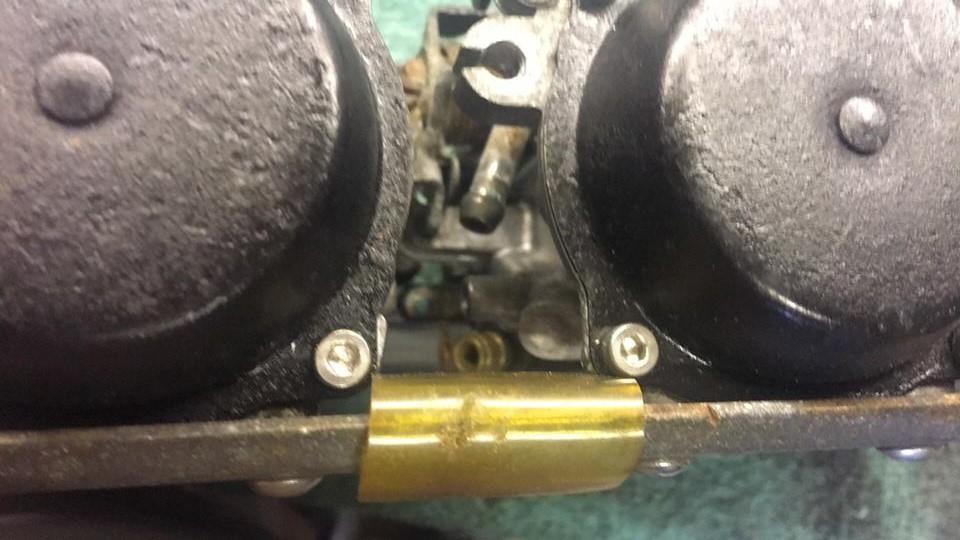
And vac spigot is tucked back between carbs 2&3
-
Yes you're right 34's. As for using both tap feeds to a T, then to single pipe to another T, to feed the 2 inlets seems a bit extreme?
-
Tap won't show anything blowing (or not) thru it cos the vac isn't working!
-
Sold to me as one off here, but not bothered cos it fits & works. Just need an idea on conns?
-
Although strangely the Slabby 7 & 11 fische says they both have only one outlet on the taps?
-
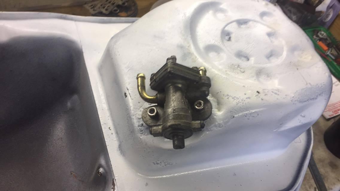
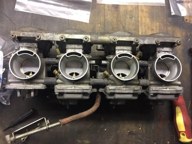
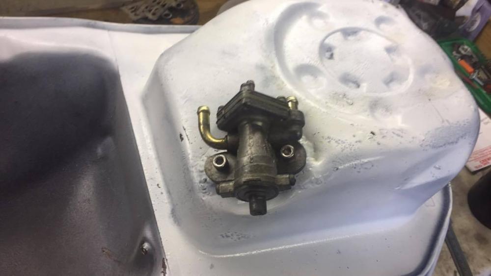
So i have a set of 36's from a GSX1100F connecting to a Slabby 11 tap. Question(s) are: On the Carbs you can see the 2x breathers near the top, 1x Vac pipe hidden between 2-3 carbs & 2x fuel intakes at the lower rail. So does it make any difference which tap exit goes to where, as one is for reserve? Also which tap outlet is the reserve too, the curved, or stumpy one?
-
That actually looks shorter at the bottom, so no need to cut away. Look at LH bottom cover hole on yours & mne to where the plate is Not much you can do to the OP switch other that file off all the castle points!
-
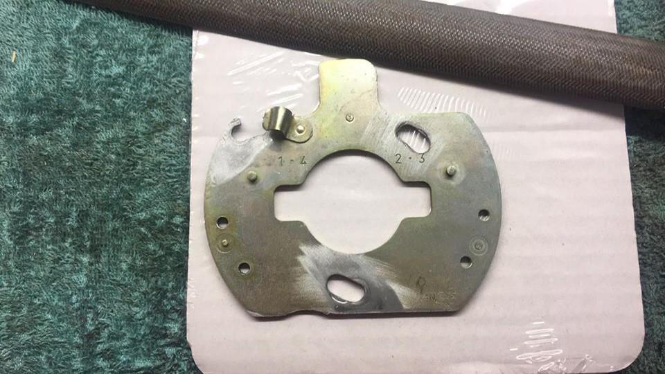
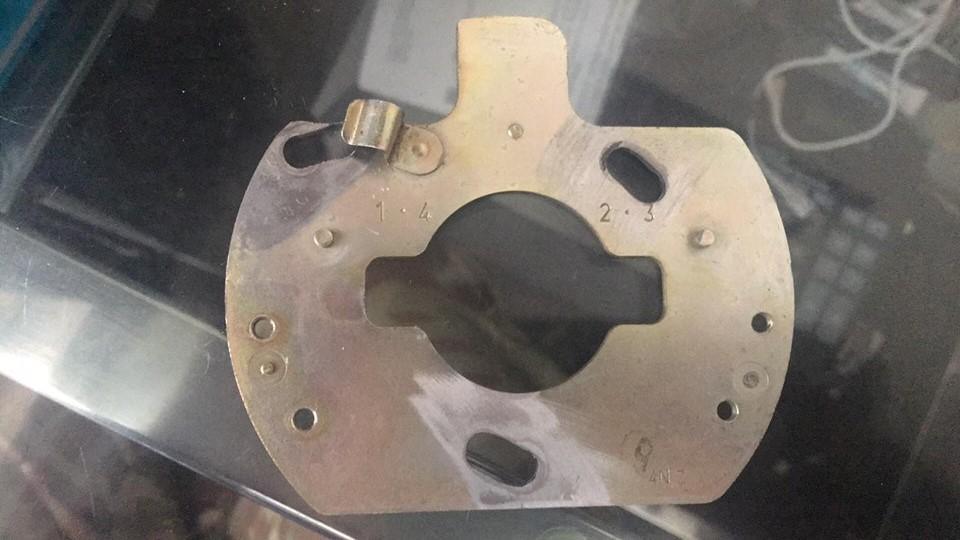
Two things i've learned in slotting this shape timing plate is: 1. The top left hole has to be cut away, it doesn't fit the obvious turn on the slot of the other 2 points. Once cut away, a 5mm washer holds it in place. 2. Next, the Op sender sits at the bottom of the plate, & once turned/advanced, the sender will not fit anymore. So you have to file a channel in it at the turn point. Pics explain it better, first is std. Second is cut out & filed channel, third is fitted

-
Duh! cancel that, i forgot the magnet spacer between the 2
- 1 reply
-
- 1
-

-
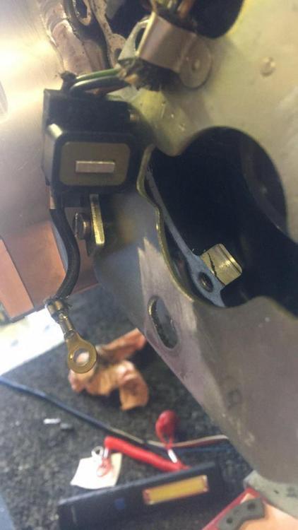
So having slotted the timing plate, i started to reassemble it. But when i put the pickup back on, it just don't sit right? It has 2x shouldered flat head screws, & they tighten to make it sit at an angle. It's like it should have 2x spacers between pickup & plate, but there weren't any when i took it off? Any ideas peeps?

-

Starter motor - going bang / kick back when trying to start 1230
CockneyRick replied to Dukeman's topic in Air Cooled
Not shown, but do both arms -
Not tried em yet, been in Salford all day
-
If i'd have done it with my shakes, it would have been S shaped
-
Here's mine done by @Rsvfletchseeing as he has tidier & steadier hands than me!
-
How strange! I have made up a fly lead for my orange trigger wire from a switched feed (Minimal Drag bike loom) Now admittedly the battery i use is on its way out & reads 10 ish volts, & when the feed is on it stays reasonably constant. However if i connect up the orange wire, it drops drastically from 10v to anywhere between 3 & 6v. This is a hefty drop, considering it's not doing anything? Any thoughts?
-
What is this "mod" you talk of, & why have you got high output voltage?
-
Well it's either an O ring, or a sprung wire circlip? Although the latter wouldn't stop it leaking, just hold it in place!
-
Starter motor - going bang / kick back when trying to start 1230
CockneyRick replied to Dukeman's topic in Air Cooled
Of course it does, i swear the Alzheimers is getting worse! Cheers for reminder. Will get it on ramp once the Drag bike is off, it & fatty need some TLC -
Starter motor - going bang / kick back when trying to start 1230
CockneyRick replied to Dukeman's topic in Air Cooled
Similar issue with the bored GS1100E. I did all the Starter clutch fixes as recommended, but i fear it has probably damaged it again. Not sure what i can do with mine as it's running a Dyna S? -
Hmm, now there's a thought!
-
Ta, was just looking at it thinking it may not turn too well. Not as round as the ones i remember!
-
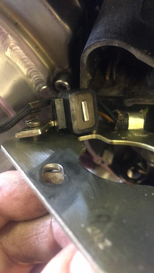
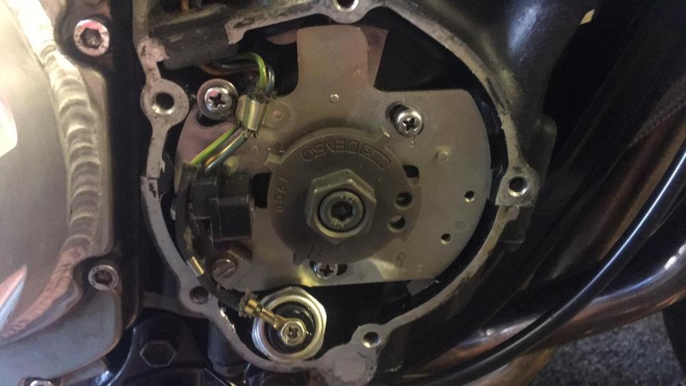
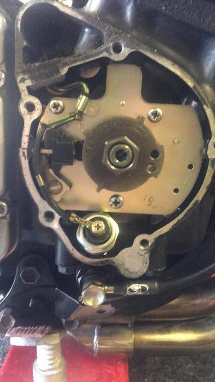
So to save money, was gonna slot the timing plate. However, having removed cover i saw this. Not seen one like it, so is the principal the same & slot the 3 screws 5mm & turn clockwise by that amount? Or would a change/upgrade be a good idea? It's a GSX1100F engine
-
Already fitted RS type seals in both wheels, so that's staying as is. Arm is a weight thing i agree, but it serves a purpose as a 1st build & RWYB. As said, when funds allow, then i'll get into the engine, look at moving battery down & back, having tank cut, decide on arm, etc etc. Just looking at simple basics, this is new territory here so don't be so rash @K.H.I
-
1st pic, assuming you are on about the wire attaching to the metal mounting point of the coil. I would suggest that whoever did it, was making an extra earth strap. Perhaps cos the mount to earth isn't very good, or they really think they need an extra one? But sseeing as the frame isn't P/coated, it seems a bit pointless. 2nd pic as far as i can see looks normal?