imago
-
Posts
2,412 -
Joined
-
Last visited
Content Type
Profiles
Forums
Events
Everything posted by imago
-
GSx1100 Dresda Solitaire (I may have had a Clivecident).
imago replied to imago's topic in Trick Frames
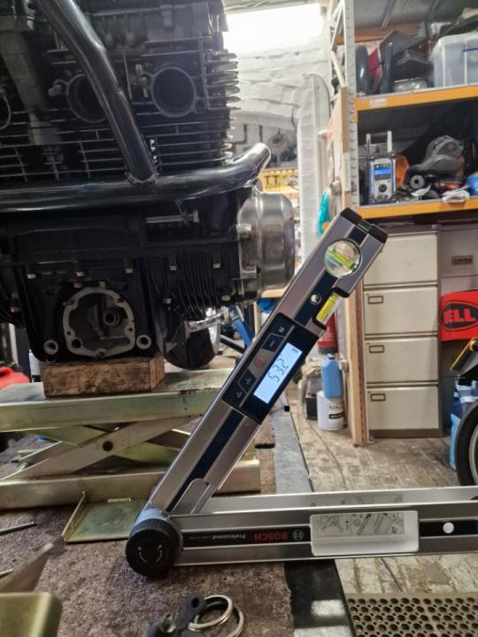
By calculation and basic measurements until it's properly mobile, but I'm getting 53 degrees for max lean angle on the Dresda with a 180 rear.
-
GSx1100 Dresda Solitaire (I may have had a Clivecident).
imago replied to imago's topic in Trick Frames
They're pretty reliable now, which means you can get the odd failure but it's rare. A bit like CDI or ignitors they rarely fail, it's usually something else which goes tits up and remains undetected until if takes them down. Earlier version did have more failures, but that was mostly down to poor installs and/or them being grafted onto a system with other problems. Electrical work remains on of the most bodged, short cut heavy and poorly diagnosed systems on bikes and cars. It's a very simple system in terms of what it needs to do (move electrons from A to B). Personally I wouldn't dream of fitting anything like an M-Unit to wiring that was more than 5 years old or had been messed about with. To me that's the same level or storing trouble as fitting new rings without honing the bores, new pads on warped discs, sticky tyres with shagged shocks etc. -
GSx1100 Dresda Solitaire (I may have had a Clivecident).
imago replied to imago's topic in Trick Frames
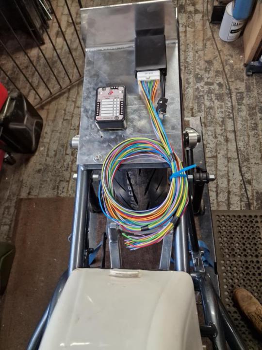
They're reliable, feature heavy, integrate with stuff off the bike via blue tooth, and massively cut down on the wiring required to make up the loom. However, if you're not going to use all the bells and whistles features for remote starting, lighting effects (pulsed brakes, hazards, headlamp delay etc etc etc. then they're just an expensive modern alternative to fuses and relays. So for the Dresda with its simple wiring requirements and no need of the features I'm using a FuzeBlock which is better than a standard analogue fuse box, but not as advanced and feature heavy as an M-Unit and a third of the price. The draw through is getting an M-Unit because it will be having a much more comprehensive wiring system and I want the features it comes with. Usual story in that it's horses for courses. -
GSx1100 Dresda Solitaire (I may have had a Clivecident).
imago replied to imago's topic in Trick Frames
A little calming work in between things. Setting up and setting out for the Dresda electrical system.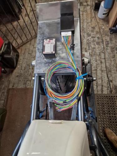
-
GSx1100 Dresda Solitaire (I may have had a Clivecident).
imago replied to imago's topic in Trick Frames
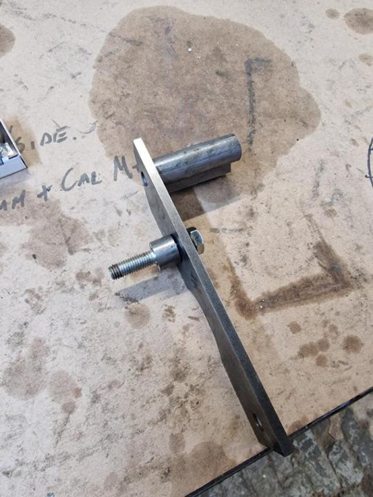
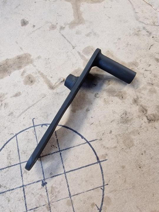
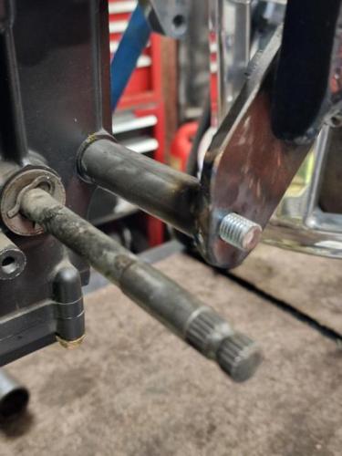
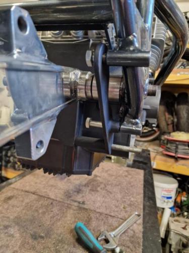
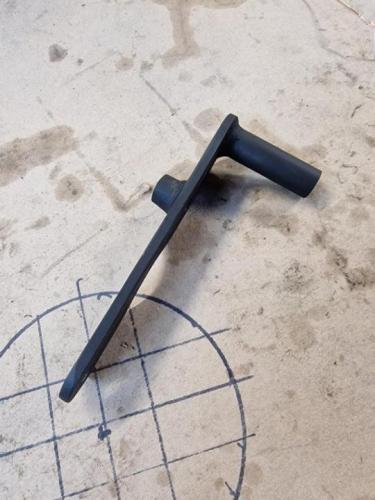
Finished making the lower rear engine mounts. I'll need to sort out some rear sets before I decide on what and where for the kick stand.
-
That's a very similar set up to Can Am MX and T'n'T head bearings, a bit over complicated but it seems to outlast taper rollers for wear.
-
Bob Ross. Nice bloke, great artist, chats utter bollocks. I've had my share of accidents, and I can say hand on heart none of them were happy.
-
Yeah, it's not a fun job. Although the last case I stripped a couple of weeks back went not too bad. I heated the whole thing, then put decent penetrating oil around the studs, heated it again, then undid them the next day. It worked OK, I wouldn't say easy, but much better. I just need to work out what I'm going to do with the kit or engine when it's done. One of those out of the blue "do you want ..." chance things that you can't turn down when they come along.
-
Thanks. I knew the block would, just wasn't sure about the cases. Probably worth taking the case along with the barells to be bored/machined at the same time then to save some faff.
-
Having never gone that big, what's involved in fitting a Wisco 1260 kit (liners and pistons) to an ET engine? Boring the barrel holes and opening up the cases?
-
@clivegtosaid some people called round asking for you.

-
I'd like to come back and enjoy your hospitality again, but it may not happen this year as August is month six of my 6 months notice on the workshop. So I imagine I'll be up to my ears in it here unfortunately.
-
GSx1100 Dresda Solitaire (I may have had a Clivecident).
imago replied to imago's topic in Trick Frames
What're you thinking for the wheels, front end and arm? -
GSx1100 Dresda Solitaire (I may have had a Clivecident).
imago replied to imago's topic in Trick Frames
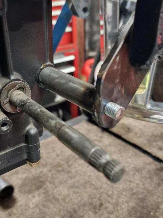
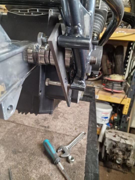
With everything in place it's out with the slip gauges to get the finish size of the spacer. 23 mm tight, 22.5 mm slip. So a 22 mm spacer required to allow for fitting and give some pinch on the arm with the spindle.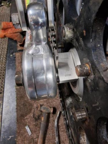
-
GSx1100 Dresda Solitaire (I may have had a Clivecident).
imago replied to imago's topic in Trick Frames
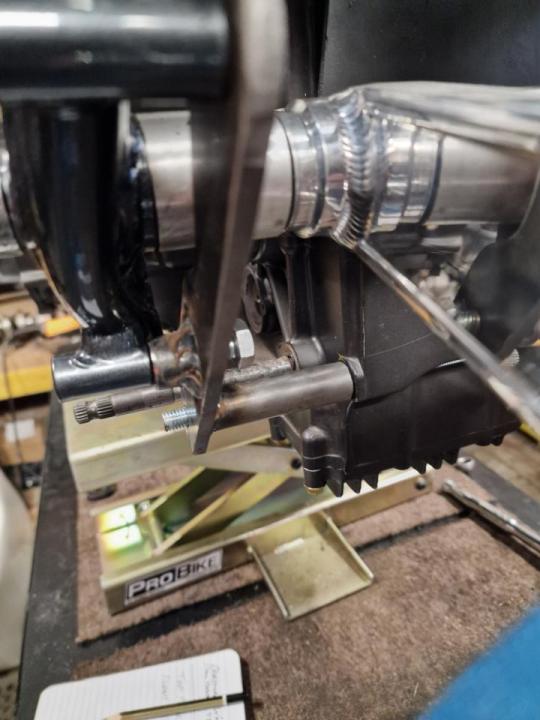
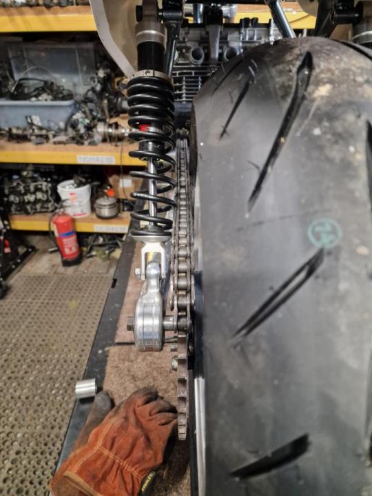
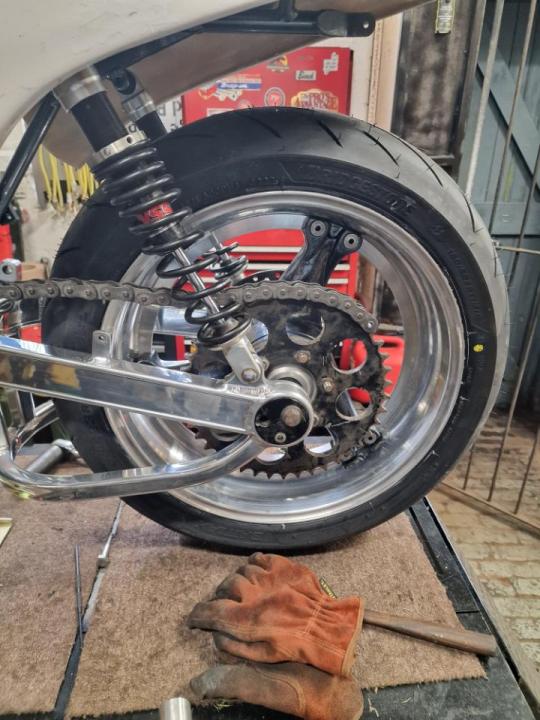
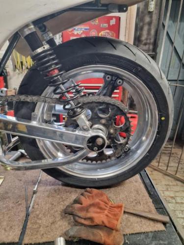
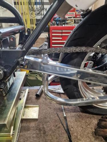
Time to see if the calculations match reality with the chain. Mock up with a 630 c&s, (no it's not an anchor chain from the Titanic!). Pretty damn good IMHO, 7mm between chain and arm with the suspension at full extension. One chain cover mount to lose, and contact with the NS shock spring. Dropping to the intended 520 will help, and I can set the sprockets in a touch. Then the bigger option would be different shocks. Basically, it works as planned/hoped/intended.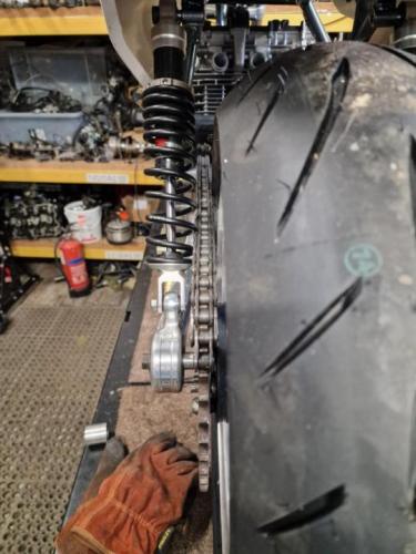
-
Because it was a great theory, but made four parts of sod all difference in practice. It also threw up a whole raft of other problems with respect to maintenance and repair. Then as time and research moved on other things brought greater gains for handling, centralising rotating mass for example which mitigates the gyroscopic effect that affects cornering.
-
GSx1100 Dresda Solitaire (I may have had a Clivecident).
imago replied to imago's topic in Trick Frames
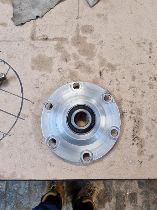
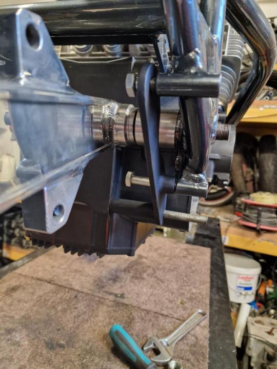
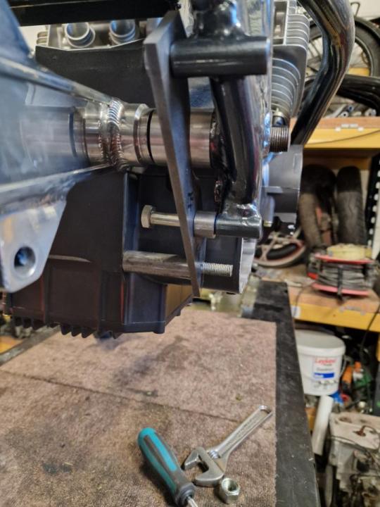
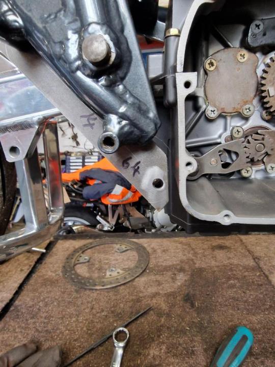
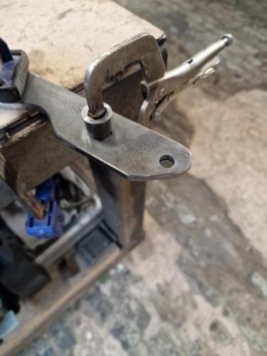
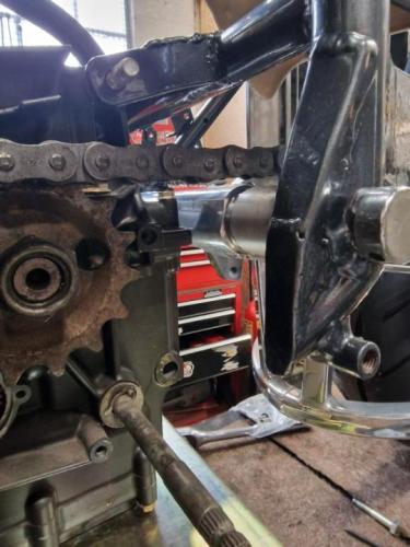
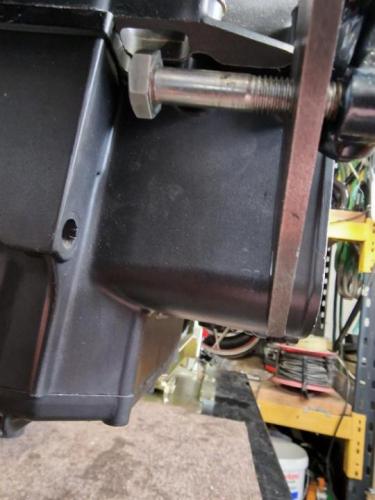
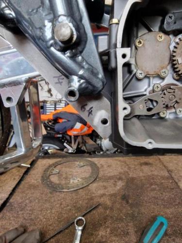
A few more bits done and boxes ticked. I'm trying to pick off some of the dull stuff while the enthusiasm is up and leave the 'nice' stuff for those can barely be bothered days. The carrier bearing arrived so I opened up the sleeve to suit and pressed it in. Then got the OS lower engine mount plate shaped up, checked it was all sitting right and sung in position, then welded the spacer tubes so that it can go on and off without faff. A quick coat of exhaust paint will keep it tidy until it goes to the powder coater with some other stuff. I'm planning on all the brackets, battery mount etc type stuff being done in black rather than matching it to the frame colour.


-
I think Haynes may have mixed up their numbering somehow? I have half a dozen ET/EX engines and they're all GSX110X-1***** numbers. One's an early engine, and two are the later ones with the additional cam cover bolts and factory welded cranks so they range from '79 to '82.
-
GSx1100 Dresda Solitaire (I may have had a Clivecident).
imago replied to imago's topic in Trick Frames
It's a good design of sprocket carrier and cush drive, and when I get bit of spare time I'm going to see if it could be adapted to fit in place of the Suzuki 'cheese wedge' set up. If so, then making up a carrier adaptor to suit would open up quite a few options for widths and fitments. -
GSx1100 Dresda Solitaire (I may have had a Clivecident).
imago replied to imago's topic in Trick Frames
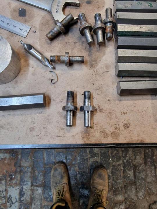
No, I was going to use some EN16 or something but when I looked at the pins and tried to find out what they were originally from it turns out that they're HadOneNeverDidAgain from CG/CB/RM etc. and they're just mild steel. The only difference between this and them is that it has six in the carrier where they're either four or five. So 6 x 9 = 54 mm means the drive is taken through over 2" of steel with rubber cushions. It should be fine I reckon. -
GSx1100 Dresda Solitaire (I may have had a Clivecident).
imago replied to imago's topic in Trick Frames
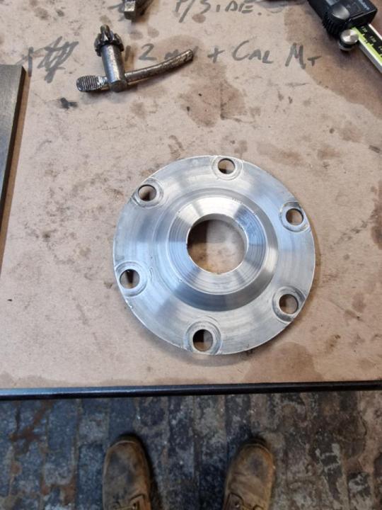
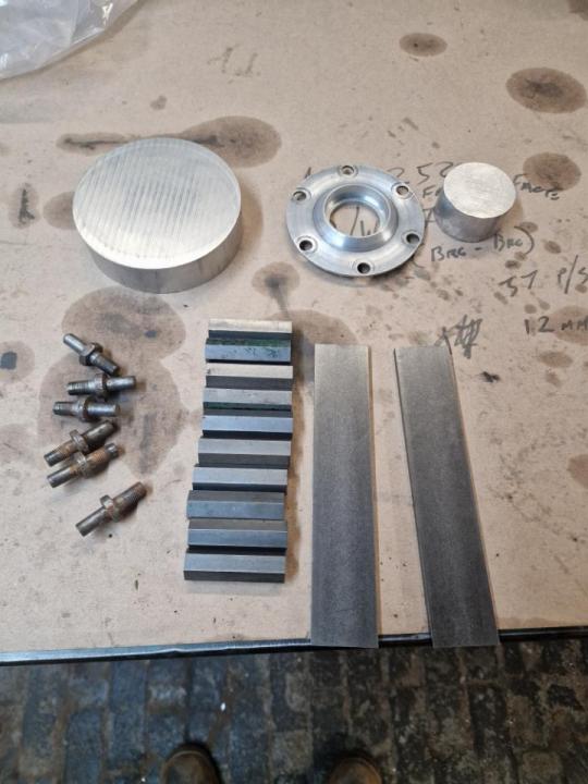
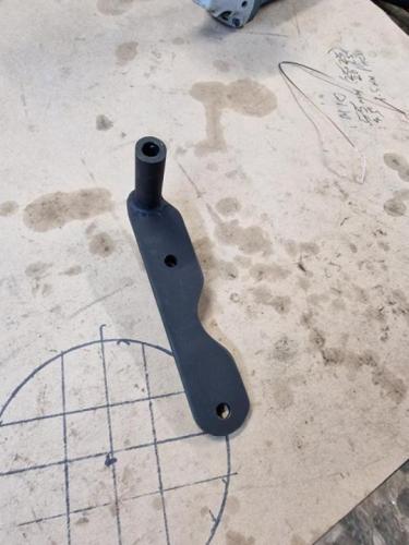
Got the sleeve made with the ID a couple of mm under size, that's pressed in now and ready to take the ID out to a finish size. Moved on to turning one of the hex bar pieces into a cush drive pin as a trial run. Worked out fine, but dull/repetitive to do and I can't do the actual pins until I see how the chain run is. So moved on to the equally exciting job of roughing out the lower engine mounting plates.


-
GSx1100 Dresda Solitaire (I may have had a Clivecident).
imago replied to imago's topic in Trick Frames
The short version of the story is, there isn't a sealed bearing the correct size for the sprocket carrier. (Supplier thought there was.) So, I now need to turn a press fit sleeve to take the size which is available. I also want to make a new carrier from scratch, along with some new cush drive pins/bolts. The sleeve will get things rolling again, and the new carrier will allow me to adjust the sprocket position, be stronger, and I just want to do it TBH. That'll probably come later though.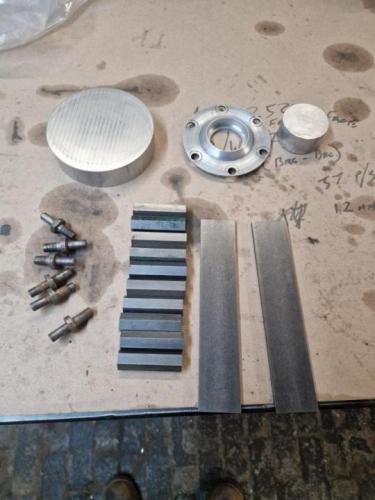
-
GSx1100 Dresda Solitaire (I may have had a Clivecident).
imago replied to imago's topic in Trick Frames
With the seat shape roughed out I can sort the battery position. Using a larger battery I have room to move it forward and down. Better weight distribution, more space on the tray, and also allows neater loom routing.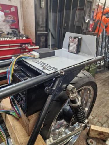
-
GSx1100 Dresda Solitaire (I may have had a Clivecident).
imago replied to imago's topic in Trick Frames
A bit more shaping of the radii required, but I think that's about right.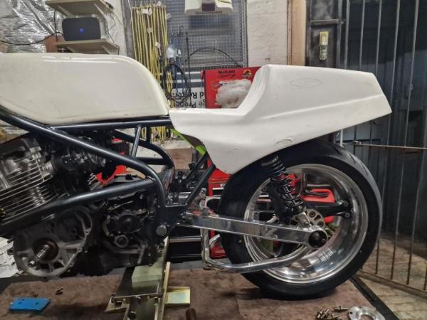
-
GSx1100 Dresda Solitaire (I may have had a Clivecident).
imago replied to imago's topic in Trick Frames
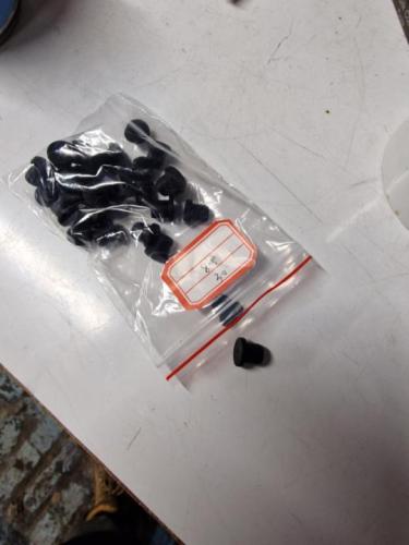
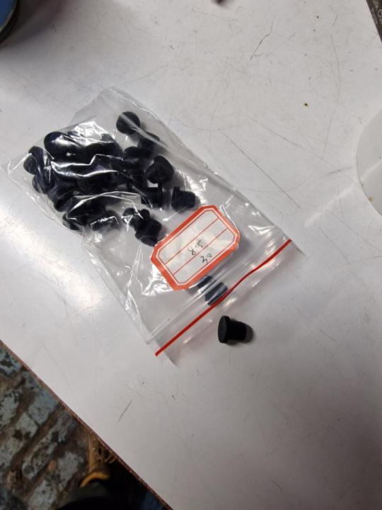
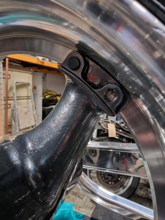
Twiddly bits make a big difference. I got some rubber bungs to cover the ugly bolt ends and prevent corrosion. Just glue them in place.