


Arttu
-
Posts
903 -
Joined
-
Last visited
Content Type
Profiles
Forums
Events
Posts posted by Arttu
-
-
6 hours ago, imago said:
Agreed. I think the only thing I'd pick up on is the difference between turbo and NA using the same port profile. Unless the port profile was designed for turbo (higher volume and velocity) then adding a turbo but keeping the secondary butterflies will move the optimum to a different rev range. Removing the secondaries will move it 'back' to an extent. I don't want to do that because it's remaining NA, the ports will be unchanged, as will the valve timing etc. So all I will 'gain' will be efficiency and smoothing out the transition through the range.
When comparing boosted and NA engines the port volume flow and velocity aren't that much different. Just air denisty is higher on boosted ones. So optimal intake tract sizing isn't much different either. The secondary plates should cause only minimal restriction when they are fully open so for high rev range it doesn't make much difference if you keep them or remove them. At lower revs where you possibly can gain something by limiting opening of the plates a turbo engine isn't making any boost so the gain would be similar for it. And even if it makes boost it would still get the gain.
-
1 hour ago, imago said:
The main part of their function is to control intake velocity on throttle opening, as you rightly point out the bottom end/low RPM side of things. The ports are sized and shaped for optimum velocity within a rev band, and below that they're too large and free flowing. The secondary butterflies modify that at initial throttle opening and lower rpm. IMHO for a NA road bike they're a big benefit for 'normal' riding. So I can see why they'd have a negative effect for something with a bloody great turbine fitted.

Generally agree with that. But open questions are how much you can affect on port velocity with the throttle blades and how big that "big benefit" really is. NA or turbo doesn't make much difference here, IMO. The same principles apply on both.
Basically the secondary butterflies do the same than using part throttle instead full throttle. Only difference is that you can automate their operation. In some cases I have noticed that engine seems to make more torque at part throttle than full open, typically at certain rpm spots at low revs. By this far I haven't systematically tested how big this difference really is, maybe I should try some day.So if your goal is to optimize all possible aspects, yes, this is something that you can try. But just a word of caution
") Over the years I have followed numerous EFI conversion projects and one quite common pitfall seems to be being "overly idealistic". This means trying to make everything theoretically right, inventing problems that don't really exist in real life and spending huge amounts of time and effort to solve these. And all that before even getting the engine started. Quite often these projects don't get ever completed. So try to avoid that
Over the years I have followed numerous EFI conversion projects and one quite common pitfall seems to be being "overly idealistic". This means trying to make everything theoretically right, inventing problems that don't really exist in real life and spending huge amounts of time and effort to solve these. And all that before even getting the engine started. Quite often these projects don't get ever completed. So try to avoid that 
-
 1
1
-
-
Yes, the secondary blades are usually removed.
It's another question if it would make sense to use them, on normally aspirated or turbocharged engines... Based on manufacturers advertisements it seems their purpose is to improve torque at lower rpms but I think their main purpose is to limit torque at lower gears and low power drive modes. Most likely they are also used to limit noise for noise certification tests. They can be used to tame down throttle response too. It's possible that you could gain some low end torque with them too but I don't know how significant improvement it would be. Most likely not very dramatic.
If you are going to use them you'll need an ECU that can support them. At minimum that would mean electronic throttle support and in addition the control strategies should support this dual throttle arrangement somehow.
As bottomline I wouldn't worry too much about them. Unless you are definitely sure that you want to keep them.
-
1
-
-
1 hour ago, jonny1bump said:
With iridium is grade structure same as ngk, so for step colder what plug is iridium.
Thank you.
Not sure if I understood the question
") For example on my bike the std plug is DR8ES, one step colder copper plug would be then DR9ES and iridium version DR9EIX.
For example on my bike the std plug is DR8ES, one step colder copper plug would be then DR9ES and iridium version DR9EIX.
In theory you want always use coldest possible plug that doesn't cause fouling during idle, cold starts etc.
-
Stock ones are fine for mild boost. For higher boost a step colder ones are good choice. I prefer Iridium plugs since they seem to result slightly better idle and they are more resistant to flooding. And they last forever. But otherwise standard copper plugs should do fine as well.
-
1
-
-
Ah, ok. I thought you were talking about switching based on boost since you earlier mentioned replacing mechanical pressure switch by the ECU. Well, boost switching by other parameters could make a bit more sense. But with this ECU setup options are quite limited. Throttle position could make some sense, lower boost at part throttle and full boost at full throttle. But I think the result wouldn't be too good with 2 stage control. RPM, maybe, but still probably too rough to be useful. One option could be safety based on engine or air temp. So normal situation would be higher boost and if temp gets too high it would fall back to lower boost.
-
Ok, let's take one step back. You have that 2 stage boost system, let's say 8lb on the gate spring and then 15lb with bleed valve, switching between those two by an electric solenoid. Now, when and why you want to switch between these low and high boost? I think typical answers are manual switching by the rider whenever more or less power is wanted or gear based switching to have less power on low gears and more on higher gears. But switching based on boost doesn't make any sense to me. Like switching to 15lb setting always when you see 5lb boost, what would be the point of that?
-
I'm afraid that you are having a blonde moment now
 (Or I'm misreading something) Usually you don't want to have boost level switched by boost pressure...
-
32 minutes ago, Gixer1460 said:
Yes if variable boost required - I was thinking more along the two step type boost control ie. low on spring only, high switch control solenoid to bleed boost for high?
Yes, that's possible but why you would want to get the ECU involved to that? Meaning when and based on what parameter the ECU should switch between low and high boost?
-
1 hour ago, Gixer1460 said:
Without all the info it difficult to confirm but couldn't the AUX1 output be used as the 'boost switching source' ? Agreed that it is a very crude solution but also (i'm again guessing here) if that output is a grounding one, it could also be hooked up to the Dyna2000 orange wire to initiate boost retard - again a crude solution!
Spent few minutes by finding and checking the manual: https://en.kms.vankronenburg.nl/media/wysiwyg/downloads/Handleidingen/English/FA23_Fuel_Manual_V3.08.pdf
The AUX1 seems to be configurable on/off style output that can be triggered by one or two ECU parameters. So it could be used as a shift light or cooling fan control. Or as boost retard control for the Dyna as you said. But I don't see any sensible way to use it for boost control. That would require PWM-style output for the solenoid and control algorithm to regulate boost.
-
1
-
-
9 hours ago, BoostedRooster712 said:
This video helped explain a few things too with regards to boost controllers.
Seems to explain the basic concepts pretty well. Misses some minor details here and there and slightly simplifies some aspects but overall a good watch.
-
1
-
-
8 hours ago, BoostedRooster712 said:
Thanks for your time Arttu, that makes perfect sense.
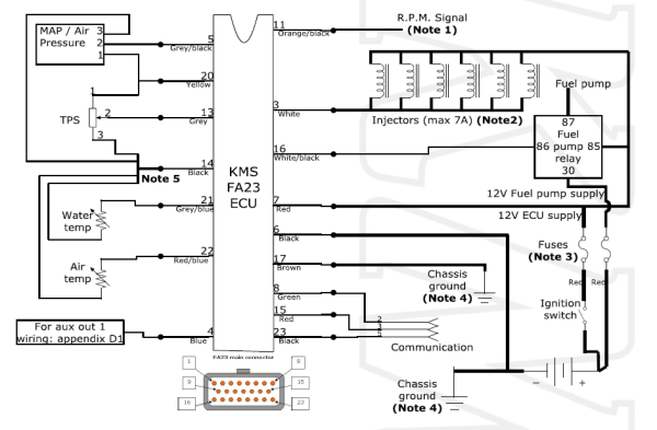
I'll cross reference the wiring diagram for the FA23 with the actual bike when it arrives and see how it has been set up.
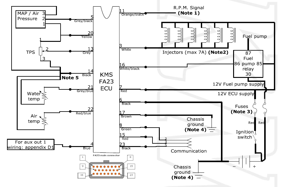
KMS sugested wiring.
I've had my eye on a microsquirt for a long while buit I'd like to see if I can get this working effectively.
That wiring diagram pretty much confirms that the FA23 is indeed a very basic ECU and most likely it has nothing to do with boost control on your bike.
It's always a though question what to keep and what redo when continuing someone else's project. And that's especially true with engine control electronics. While I'm sure that what you have there now can be made to work just fine I would be very tempted to just rip off everything and start from a clean sheet with some more capable ECU that can do everything. But that's because I'm an engine management geek and don't mind about tinkering with these things
So I can very well understand that some people wouldn't want to touch that if it works already.
A Microsquirt is one good option for simple but capable ECU. Although there are some other similar ones on the market which might be even better depending on what you want. Just let me know if you need help with palnning.
-
I'm not familiar with the KMS ECUs but the FA23 seems to be a very simple fuel only ECU so I assume it doesn't have anything to do with boost control. In that case there would be some separate boost control arrangement. The simplest option could be that the switch is directly controlling the solenoid valve and the valve just switches between low boost that is pressure going directly to the wastegate and high boost where pressure is routed through some bleed valve. Alternatively there can be some separate electronic boost controller controlling the solenoid valve and then the switch is used to change target boost of the controller.
So I think you need to dig down and see what's actually there and how everything is connected.
MAP sensor problems are unfortunately quite fundamental. The ECU uses the MAP sensor to measure the boost and based on that adjusts fueling. So if the MAP sensor doesn't read correctly the fueling will be off which is naturally very dangerous situation. So this definitely requires proper checking before running the engine under any real power.
-
2
-
-
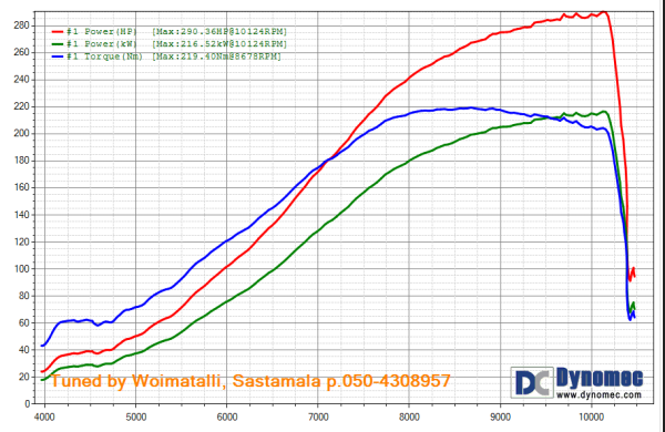
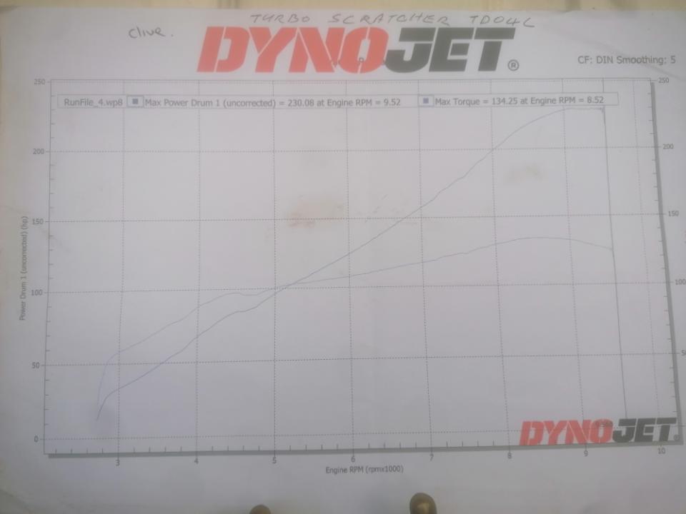
15 hours ago, clivegto said:
@ArttuI got just over 230hp with tdo4l on 1216cc busa pistons big valve flowed head
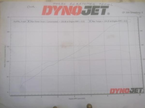
What TD04 variant it is? The range of TD04 models is pretty wide, smallest ones will max out before 200hp and biggest ones can go over 300hp. Based on the torque curve it looks like the boost climbs up with revs?
-
Hmm, not sure if I can follow your thoughts. What's the another red dot on the bottom of the map?
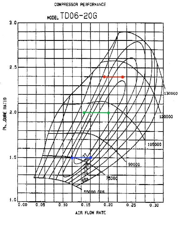
All right, let's do some more compressor map analysis. (Warning, some numbers and theory stuff ahead!)
First let's see what kind maps we can find for the TD05-20. I found basically two different maps from the net. Both are actually for TD06-20G but since the compressor side is the same (20G) they should be fine. Another one uses kg/s mass flow and another one CFM volume flow. The maps are shown here side by side. By closer look it seems that the maps itself are the same and another one is just converted to different units. I'm pretty sure that the kg/s map is the original one and the CFM one is probably converted by some random guy. Also it looks like the conversion is somewhat "optimistic". So let's use the kg/s map for analysis.
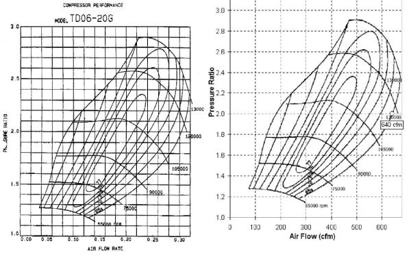
By quick look on the map we can see that highest presure ratio what it can reach is 2.9 which means 1.9 bar boost in typical conditions. So yes, if you need over 2 bar boost this clearly isn't the right turbo. Maximum mass flow is 320g/s and 300g/s can be reached with boost between 1.0 - 1.6 bar. Rule of thumb for converting mass flow to engine power is that 1hp needs about 0.8g/s. This can naturally vary between the engines but it's accurate enough for this kind purposes. So maximum realistic power for this turbo would be around 375hp.
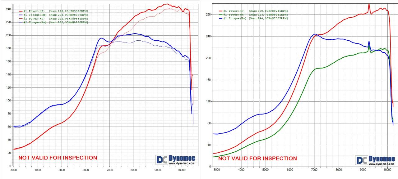
Then we are going to cheat a little bit and use real life data to estimate where we would land on the map with this 1216cc oil cooled engine. Here I have dyno graphs from a Bandit using this turbo, 1.0 bar and 1.4 bar. The engine was 1186cc, ported head, GSX-R1100 cams. The pistons were flat tops and 2mm spacer plate was used so compression was pretty low. No intercooler but water injection was used.
At 1 bar full boost was reached around 6500rpm and engine made there about 185hp. Maximum power slightly under 250hp. Mass flows respectively 148g/s and 200g/s. At 1.4 bar full boost at 7000rpm and 240hp, max power about 290hp, mass flows 192g/s and 232g/s. I don't have graphs for lower boost but for 0.5 bar I would guess full boost at 6000rpm / 150hp and max. around 200hp. Mass flows 120g/s and 160g/s.
As side note these power figures were a bit lower than I would expect in ideal case. Probably due to low compression and bad combustion chamber shape. So it's possible that actual air flow figures were slightly bigger than estimated here.
So finally we just need to plot these numbers on the map. 0.5 bar shown in blue, 1.0 bar in green and 1.4 bar red. So here we can see that on all these boost levels we are nicely on the map and even on pretty good efficiency area. If the engine can be made to flow better, for example by adding an intercooler, the operating points will shift to the right to higher flow. And there is still some flow reserve available for that.
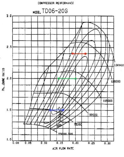
So I would still say that this turbo suits pretty well for a Bandit/GSX-R engine around 1200cc when using boost between 0.5 and 1.5 bar. Maximum power will depend on how well the engine flows. I guess about 320hp should be possible without intercooling if the engine is done right. With intercooler even over 350hp should be doable.
-
2
-
-
8 hours ago, Fredrik_Steen said:
I'm guessing it's the maxspeeding brand you are looking at. It's cheap
Looking at similar compressor maps I don't think it's the best choice out there for your application.
Care to explain? Based on maps that I found it might be slightly on large side, depending on which map you believe. But still my flow estimations for 0.5 to 1.5 bar boost range seems to fit quite nicely on the map. And in practise it seems to work fine too. Although, if good response is preferred over maximum power a smaller TD06-16 variant might be a better choice.
Of course if you mean the absolutely best by "best choice" I agree
It's a budget choice after all, especially when using those cheap copies. But most likely works just fine any ways.
-
53 minutes ago, Jdeac said:
I get the basics but say gt2860r OK it's then the numbers (ar) where I'm getting lost. .60 .70 .80 hot side cold side
Like I was told by a turbo builder. Holset he221w good for 280bhp but then there is 5,6,7cm etc sizes
I'll keep watching. And try grasp it.
Typically compressor and turbine wheel sizes are fixed within a turbo model. And usually compressor housing is fixed too. But for the turbine housing there are often different size options. Some manufacturers use A/R ratio (like 0.84) and some turbine throat area (like 8cm2) to specify the size.
Turbine housing options can be thought as fine tuning for the base turbo model selection. Basically bigger housing means lower exhaust pressure and hence more power at the same boost. As flip side it also means later spool up and slower response.
-
57 minutes ago, Gixer1460 said:
The two responders here are a damn sight brighter and cleverer in respect of this stuff and understand the numbers - something that has defeated me, so i'm a 'try it and see' type for development LOL! If I do another build, I will deffo use a BB type core, Maybe Garrett 28R or 30R based - its the housings and wheels where the secret sauce is hidden so listen to the two guys above!
Well, there is still plenty of "try and see" even after munching all those numbers
But knowing the basics and doing your homework can improve your chances significantly.
-
9 hours ago, Jdeac said:
Your saying a td05 20t (not looked into that yet) would get me in the high 200's able to turn it down (boost wise) for the road.
Yes, TD05-20 or TD05-16 should be a good basic choice for approximately 200-350hp power range. If you don't need over 300hp another option could be TD04-16 that should spool up earlier and provide better mid rpm power.
Just be aware that it can be somewhat tricky to get low boost, below 0.6-0.8 bar, with the internal wastegate on these. Standard actuators on these are usually around 0.8 bar. The actuator can be changed to lower pressure one but then you will probably face boost creep since the gate can't flow enough to keep boost down. This can be improved by porting the wastegate hole but still you probably will struggle to get below 0.5 bar at high rpm.9 hours ago, Jdeac said:Td04/5 are 3 bolt flange correct...or can any turbo have any flange?
Availability of flange types depends on what kind exhaust housings have been made for that particular turbo. Typically there are few different flange types available for each turbo model. Aftermarket performance turbos typically use 4-bolt T25/T3/T4 flanges or round v-band flanges. OEM car turbos use these too but in addition there are numerous car specific flange types like those 3-bolt ones.
TD05 turbos seem to be available with both car specific (Subaru) 3-bolt flanges and generic T25/T3 flanges.
-
14 hours ago, Jdeac said:
As much as I can. The occasional strip action. But will mainly be a road bike. But it's always nice to have it there if you want it. If that makes sense
Not the best possible answer
You can get almost as much power as you want, up to 600hp or so. But sizing the turbo for bigger power comes at cost, meaning later spool-up, bigger lag and worse efficiency at lower power. So it's better to set some realistic goal for maximum power and select the turbo for that.
To get the discussion going let's pick some examples, starting from low end of the price range.
-
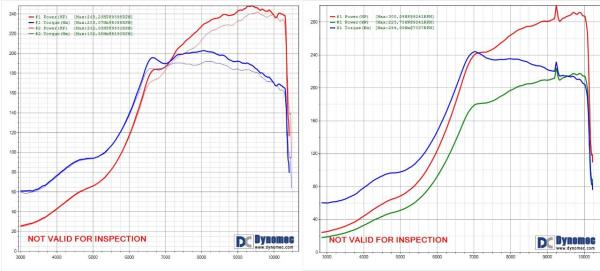
Mitsubishi TD05-20. Actually this is cheap only because there are plenty of Chinese copies on the market that seem to work just fine... Maximum power maybe around 350hp. To give some idea here is a dyno graph from a very similar engine that you have, 1 bar boost.

-
Holset HX35. Not the most modern design so spools up a bit slowly and maybe doesn't make the best power for boost. But capable for way over 400hp especially at higher boost levels. Size is pretty huge. Again dyno example from very similar engine, 1.3bar boost.
- Garrett GT2871R. Over 400hp. Ball bearings, spools up pretty much like the Mitsu TD05-20, most likely makes more power at the same boost. Physically smaller than the Holset HX35.
- Xona Rotor XR 4951S. Maximum power probably around 500hp. I don't have first hand experience about this exact model but based on some bigger one these are pretty much the best shit that you can get. Makes really good power for boost and spools up well compared to the power capacity. Very lightweight too. But mucho $$$...
-
2
-
Mitsubishi TD05-20. Actually this is cheap only because there are plenty of Chinese copies on the market that seem to work just fine... Maximum power maybe around 350hp. To give some idea here is a dyno graph from a very similar engine that you have, 1 bar boost.
-
1 hour ago, Jdeac said:
Forgot to say it's also all the numbers of hot and cold side that baffle me.
IMO wheel sizes and housing AR numbers aren't very useful since they vary between manufacturers. Meaning that for example 50mm compressor from Garrett might be very different than 50mm from Holset. So they can be used mostly to compare turbos from the same product family. Of course if you happen to have some mystery whizzler without any info then you can get some idea from the wheel sizes.
-
One very crucial piece of info is missing: How much power you want?
-
-
Well, I think there are few different typical methods for ignition timing:
- Just use something that you have heard elsewhere or what you have used earlier. Hope for the best. Turn it down a bit if the engine melts.
- As above but try reading plugs and listening the engine before meltdown.
- Use dyno to find optimal power timing. If there seems to be wider window without significant change in power use lower end of the window. Otherwise as above.
Being knock limited can vary a lot depending on compression, boost, fuel and other variables. But based on my experience turbo bikes are surprisingly rarely knock limited if they have been built even somewhat sensibly and if you don't push the boost too far. So if possible I try to stay at "comfort zone" and then just use dyno to find optimal timing.
-
1


GSXR600 TBs
in Forced Induction
Posted
As far as I know boost doesn't flatten the intake pulses and resonances. That should work just like on NA engine. Only resonance frequensies / rpms may change a bit due to higher pressure and temperature. But relatively these are less important on boosted engines since by modest boost increase you can easily get bigger power increase than by matching intake resonances perfectly.