


Arttu
-
Posts
907 -
Joined
-
Last visited
Content Type
Profiles
Forums
Events
Posts posted by Arttu
-
-
41 minutes ago, Jaydee said:
If only one guy was helping you, he must have been put in some amount of effort.

Effort was shared between three guys so it wasn't too bad in the end.
-
 2
2
-
-
Carbide end mill bits can also do wonders sometimes. Once I had to enlarge a hole in a hardened steel bushing. A cobalt drill couldn't do anything to it and I was almost giving up but then thought to give a try for a mill bit. And for my surprise it went like into butter.
-
12 hours ago, wraith said:
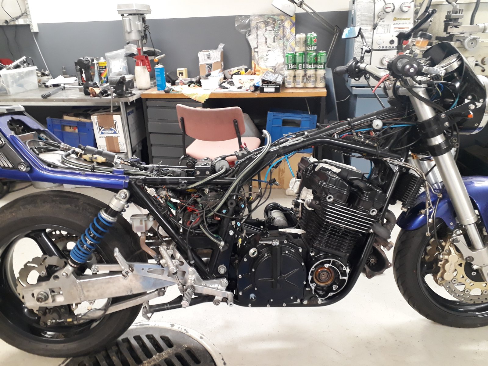
Best way of fitting a engine in the frame, get some mates round, get some beers in and stand and whatch them do it for you when you sit and drink the beer
") but save them one or they won't come and help you next time
but save them one or they won't come and help you next time That's pretty much how my last engine installation went. Amount of required effort can be seen on the table

-
4
-
-
1 hour ago, Gixer1460 said:
I just looked in the Haynes for the GSX1100 / 1150 and that shows the metal centre of the seal facing out ie. opposite to how it is above. Not sure how different the GS1000 would be, if at all!
Yep, metal side out is how I think it shouid be. And how it seems to be in the manual pic above.
-
1
-
-
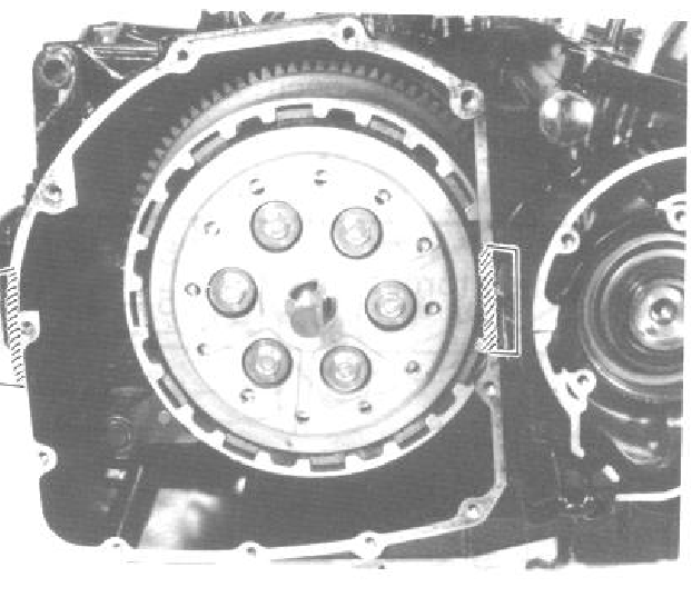
I think it should be other way around but unfortunately I can't remember where I checked it from. Even the workshop manual doesn't tell that clearly. But for example in this picture it probably is other way around. If you take a close look on the seal you can see the lips are different compared to normal oil seals. Mine was weeping slightly when mounted wrong way. But if your's doesn't leak then there shouldn't be anything to worry about.

-
3 hours ago, Reinhoud said:
Looked up the partnumbers, GS1000 and GSX1100 have the same oil seal.
How did you tap it in?
Can't remember exactly, it was few years back...
Btw, are you sure you have it there right way around? That was the reason why I had to take mine out.
-
Not sure about the GS1000 but I have done this with a GSX1100 successfully. I think I drilled a small hole on the old seal to pry it out. Then just carefully tapped in the new one.
-
I think you have to do some leg work for compression ratio and cylinder spacer questions. I mean if you want to get good results. Here's how I would tackle that:
- First you need to decide what compression ratio you want. Variables are the usual ones, how much boost, what fuel, do you have charge cooling and so on. I guess you will need something like 22-30 psi boost and proper intercooling to reach your 400hp target. On pump gasoline I would probably aim for 8.5-9:1 compression. With race gas or E85 something like 10:1 should be good.
- Piston to head clearance (squish gap) should be around 1.0-1.5mm.
- Then you need to measure and calculate the actual compression ratio with your pistons. Quite often advertised compression ratios for pistons are very inaccurate so your 10:1 pistons might be actually 9:1 or 11:1.
- Now you know how much you need to change the compression and you can check how to do that. One good option for minor adjustment is to machine piston tops if there is enough meat on them. If you machine just the dish in the middle of the top you can keep the squish band and proper combustion chamber shape. You can also adjust the squish cap within the range mentioned above. Also one option is to remove material from the head but that has relatively small effect if you don't ruin the shape completely. As last resort you can throw the squish band out of the window and increase the gap even more. But that will most likely hurt efficiency and possibly increase knock sensitivity.
-
1
-
All the EFE engines had factory welded cranks and some of the earlier E models had too. I don't know (or recall) the exact point when the E models started to have welded cranks but it's somewhere around '82. Maybe at the same time when they switched to bigger taper on the flywheel.
The factory welded cranks are good for some power if they are otherwise in good shape. For example my stock '83 E engine was running fine for quite long time at 200hp power. But if you are looking for some serious power and want it to be reliable too it's better to get the crank checked and built by someone who knows these cranks. The factory tolerances are too loose for serious use.
-
1
-
-
7 hours ago, TiZiK said:
Thanks Arttu for that link. It was actually really helpful.
So I did a quick test on the fox shock. I pulled all preload off the spring, backed off the compression and turned rebound to max. Well, I think this shock is more than adequate. At those settings, It takes almost a full minute to revert back to its original height. Took a few turns out of the rebound and it currently rebounds at the same rate as the s1000rr in Brocks video. About 3 seconds to revert to original position. As I'm all of 160 lbs, I think I will need a lighter spring as I can only get it to squat around 2 inches (measured from the swingarm to the very back tip of the subframe)
I guess the best thing to take away is that the valving is up to the task.
Thanks again Gents for the replies. Sometimes I just need to talk it out with others who can offer a different point of view.
It's actually pretty much best info about drag shock adjusting that I have found on the net. And lines up quite well with my personal experience.
Sounds like you can at least start testing with that shock. Finding a correct spring may require some experimenting too since it's slightly different game than for a road bike. For example amount of power and how quick you are going affects to selection too.
If you have a data logging system I highly recommend getting a shock travel sensor. That helps a lot for finding working setup. Without logging you can try to be creative
") For example install some pointer showing the shock position and put a GoPro filming it during a run. Or at minimum get a friend to film your launches so you can see how the back end reacts.
For example install some pointer showing the shock position and put a GoPro filming it during a run. Or at minimum get a friend to film your launches so you can see how the back end reacts.
-
If you can do rebuild and revalve I guess you can get it quite good after a couple of trial-and-error rounds. That's always one option if you want go fast without spending much money

For reference here is one quite good video that should give you some idea what you want to achieve with the rear shock.
-
3
-
-
Pretty much as said above. It's very ulikely that any OEM shock just thrown in would work even half decent way.
Long swingarm means that you will need stiffer spring just to compensate linkage ratio change. Then in drag racing rebound of the shock needs to be very slow compared to any other usage. So combined with stiffer spring this means you need really stiff rebound damping. Compression damping probably can be quite normal.
So I would say you have basically two options:
- Get some shock that is specifically made for drag racing. Like Penske or M2. These are either built to your specs like weight, swingarm length etc. or they have wide enough adjustments to cater most of the cases.
- Get some rebuildable and adjustable "normal" shock like Öhlins, WP etc. Then find some shock specialist that understands what is needed in this application and can rebuild the valving to get suitable damping.
-
1
-
It was quite painful to follow the translated subtitles but the main idea came through, I think
-
1
-
-
I think lowering the IC should be relatively easy. I guess you have to modify the end tanks any ways?
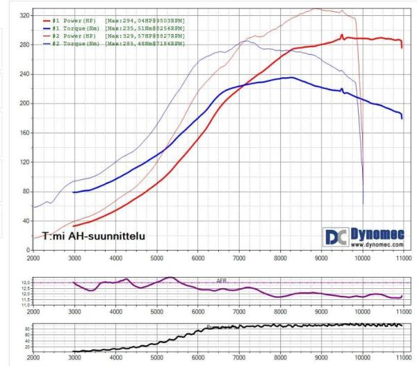
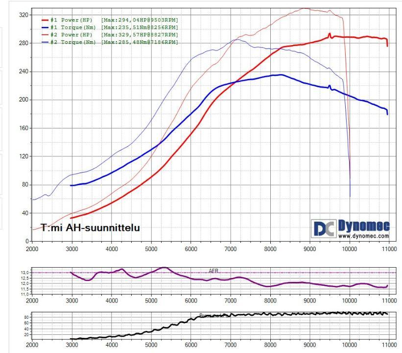
All of those turbos should be good for that power. I don't have too many comparison results between those but I think the GT28xx should spool up a bit earlier than the TD05. At least if the Garrett copies are close to original quality. For example here is comparison between gen2 Busa (1340cc) with a chinese TD05-16 and gen1 Busa (1300cc) with genuine GT2871R. The maximum boost is about the same on both, about 0.9-0.95 bar. The gen1 was also intercooled and running on E85 which probably explains most of the power difference. But I think those should have only minor effect on spool-up.
-
1
-
-
Haven't tried that with MaxxEcu but I think you should have something else than 0 in "MAP Dip Threshold". I would start experimenting from 10kPa or something like that.
-
Audi / VW 2.0 TFSI engines have pretty thin IC, only 32mm on some models. But otherwise the cooler is huge, about 600x400mm, so probably not good for your project.
-
1
-
-
Hi,
Nice to see your project here too!
Regarding the idle control valve, I haven't used them on any of my EFI projects by this far. In my opinion it's more like luxury than essential thing. Basically you need it only if you want to keep the idle rpm exactly stable without any manual intervention. Especially for a race bike this isn't a big deal, IMO.
-
12 hours ago, gtecomp said:
2. dead time/voltage correction table of stock say what now!? 600 injectors. Before 7 years I put some weird values and I don't remember from where I get them.
I'm using 0.9ms dead time at 13V and approximately 0.15ms/V voltage correction for them. These aren't 100% correctly measured values but close enough to make it work just fine.
I have several ignition tables for 1100 oil cooled turbos and maybe even some for a 750. But if there is some example table on MaxxECU site it's probably as good starting point. There is always some variation between the engines so in the end you have to tune your own in dyno. Copying the VE tables is even less useful. In addition of differences between the engines there are also numerous variables in the ECU setups, sensor calibrations etc. that affect on the VE table. So based on my experience it's always pretty much full re-tune for every engine.
-
5 hours ago, GSX1100dreamn said:
Arttu my trigger wheel is timed when at #1 TDC the pickup is positioned between tooth 7 and 8 where the red mark is above, the arrow on the trigger wheel is also correct for engine rotation. So #1 TDC the sensor is between tooth 7 and 8 after the -2 gap.
Phew.
If I followed this correctly this means #1 tooth at 100° BTDC. Which makes sense since this seems to be common choice on Suzuki EFI engines.
Regarding sequential operation without cam sensor. First, having separate output channels for each injector and coil doesn't necessarily mean that the ECU runs sequentially. Coil and injector faults are usually detected by current so the ECU doesn't know if the cylinder is actually firing. However, there are a couple of ways to figure out the engine cycle without cam sensor. One is to use MAP sensor to detect intake stroke. I know this is used by some OEM bike systems and some aftermarket ECUs are supporting this too. This usually requires connecting the MAP sensor only to one cylinder which may result other problems with MAP signal stability. And more or less tweaking might be needed to make it work properly. Another method is looking crankshaft acceleration and detecting power stroke from there. This is used by many OEM car ECUs for misfire detection but I don't know if it's used for sequential synchronization anywhere.
-
First tooth after the gap meets the sensor at 100° BTDC.
-
13 hours ago, gtecomp said:
I share the idea of OEM 4 tooth sensor with my tuner ...and he doesn't like it. He states that in forced induction - more accurate ignition timing is needed as far as 5 deg more or less means destruction of engine . Maybe he is right.
Yep, I would call that 4 tooth wheel as "risky option". It may work or it may cause some unexpected troubles.
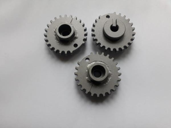
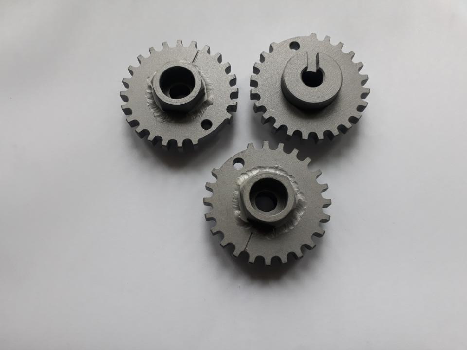
If needed I can supply a 24-2 wheel that bolts on to oil cooled engines and works with the stock sensor.
-
2
-
-
2 hours ago, Fredrik_Steen said:
The change to a new sensor was relatively easy, I used the oem base plate and added a tab to mount the sensor
Love your new dyno, it looks awesome!
Would be fun if you documented your Maxx instalation on the bandit here on this page
")
Yes, not a huge project to change the sensor. On the other hand changing the wheel isn't difficult either. Undo the bolt, remove the wheel, insert new wheel, tighten the bolt. That easy!
Thanks! There is still plenty of smaller stuff to do for the dyno but it's indeed pretty useful already.
Let's see if I have time to document the Bandit installation. It's my friend's bike and I'm doing just the EFI stuff for it but might be worth of a "mini project thread".
-
2
-
-
Yep, definitely shouldn't hurt doing it that way. My main point was that there shouldn't be any fundamental problem with your current setup either.
-
3 hours ago, Joseph said:
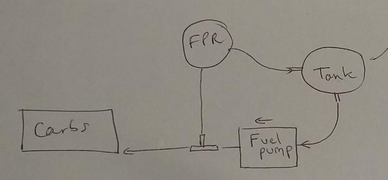
Despite your explanations I don't understand why my system is fitted like this :
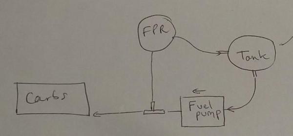
Like said, that works the same than if feed to the carbs would go through the regulator. A return style regulator keeps the whole pressurized system after the pump at the same pressure. In that regulator picture both "high fuel pressure in" and "to carburettor" connections go to the same chamber so that second connection is essentially just a T piece that is integrated into the regulator body. (Disclaimer: haven't checked exactly that Malpassi regulator but all the return style regulators that I have seen are that way).
So if the regulator works like it should there isn't any "high pressure" anywhere in your fuel system. The highest is what the regulator is set to.
1994 Turbo RF build
in Forced Induction
Posted
So are you going to run it without intercooling?