Baz1954
-
Posts
27 -
Joined
-
Last visited
Content Type
Profiles
Forums
Events
Everything posted by Baz1954
-
You will need a spacer for the front sprocket nut. 3mm I think, did it about a year ago.
-
Thanks for replies. I have had the two removable headers done (they are double skinned). I have cut the baffles out, amazed that they are only about 150mm long. Wrapped with felt. My guy has already sighted the system and will charge $AUD 1,500 to chrome. Going to go ahead with assembly process I described above.
-
Twin discs.
-
Thanks for the replies guys, but I live in Oz there are only about a dozen bikes on this island continent and less shops. I'll keep looking.
-
Yet another question Re: 1978 Gs1000. Is there an equivalent front brake master cylinder kit. Cannot find OEM no. 59600-47811. Anything that comes up is N/A. One site sent kit that ended up being for GS750... much smaller parts. Other advertised parts have a helical running down half the piston. Thanks.
-
As I stated before, I'm in the process of rebuilding my '78 GS1000. I'm trying to return her to original. For example I had to source foot-pegs, swingarm, brake hoses and other parts I ditched when young and dumb (instead of hanging onto them). Same with the exhaust system. I shipped an original exhaust system from Houston TX as there nothing here in Oz. It needs re-chroming but the problem is the mufflers have to be removed or no-one will do it. My plan is to cut the ends of the mufflers off at about 20mm from the ends and withdraw mufflers, then weld tube to inside of the end with muffler attached. Now I should be able to push the muffler back in and drill four radial holes around the main muffler tube, withdraw the mufflers and weld nuts to the inside of the tube I welded in at the holes I drilled. Now I should be able to remove and replace at will. Hope this makes sense and maybe someone has done a similar operation before. Thanks.
-
I have the exact same seat bought in UK around 1980.
-
I got it out Reinhoud and I'm going to go the peroxide way to lighten it, I'll post result in a couple of days. I love this site, access to info and parts as well. Thanks for the offer.
-
Ok, thanks BigT will look into that.
-
I'll check out the 'sterilising'. As for 'o' ring I rate them as one of the greatest inventions ever. Used them a lot when I was a submariner. So prefer manufactured. I wondered if there should be a comma after babies LOL.
-
Thanks for that Rijko, I'll save site in-case I have any problems. The 'o' rings site I ordered from don't ship to Oz so going thru a buddy in UK. The shipping cost for that reservoir is a bit "out there" but if I have to I will. Thanks
-
Discontinued and couldn't find any on the net. Found OEM 'o' ring for it in Germany (again discontinued). It was still quite flexible although a little opaque compared to original.
-
Got it out with no damage. Four hot and cold dips.
-
Will do Toni. Thanks
-
Guys/gals I'm back with another question re my 1978 GS1000. I'm overhauling my brakes replacing master cylinder internals and I want to replace the 'O' ring under the front brake reservoir. Tried putting it in hot water to see if expansion would help remove the reservoir but no it didn't. Somewhat wary of breaking the reservoir as I cannot find any online if I do. Do not want to replace assembly with rectangular type. Any ideas? Thanks
-
LOL, certainly do, been that long since I stripped her down. the manual I'm using is as old as the bike. Most things are obvious and manual not needed other than for dimensional specs, torque settings and the like but that just did my head in. Did a total do over on my TLR no problem other than checking specs.
-
Definitely OEM. Still have the original (broken) and it does not have any sealant. I was thinking that I will seal it. So in the end I was thinking too deeply and buggered myself up. Good thing you guys are here. Thank you for your response.
-
Oh dear, Just mounted as you directed and hey presto! neutral light came on. Also gave myself an uppercut. I had thought about this way but didn't think it correct as a large part of the contact is exposed. Anyway thanks for the responses. I can progress now. I'm putting her back to original and will post pick when finished. Taking a long time, for example I sourced an original exhaust out of Houston Texas and it needs to be re-chromed.
-
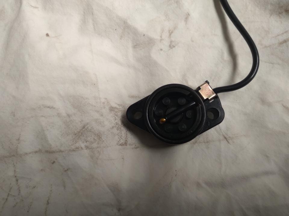
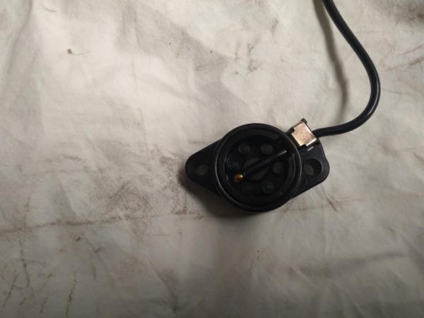
Here is image of internal side of switch + 'O' ring.
-
No, I'm afraid not. The images above show the external view. The 'dot' you can see is the back of the contact which has a greater surface area for contact with the spring loaded pin.
-
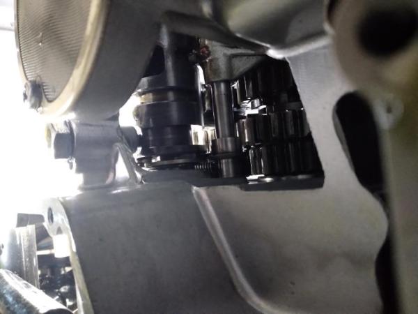
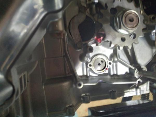
Yes guys, I have a New Old Stock switch from Suzuki (Australia),the original had a crack in it. As you point out both bottom images in replies show correct orientation of pickup (5 o'clock) whereas the spring loaded contact on the end of the shift cam is sitting at around 2 o'clock. None of it is making any sense: the cam is in neutral, I can shift thru the gears ok. That's why I'm wondering if the cam is not one complete machined item and that the sensor end with the spring loaded contact pin is a press fit and I may have disturbed it somehow to the 2 o'clock position. Thank you both for the feedback.
-
This is a Hail Mary but I'm wondering if the neutral end of the shift cam is a press fit into the cam body and may have been disturbed into the position shown above. If anyone has access to one I would appreciate a check if not I will have to buy one as I cannot figure out this problem. Thanks.
-
-
Thank you TonyG for your reply. There will be delay with replies as I'm in Oz. Rotating engine by hand in neutral all gears that should are turning. When I fitted the shift cam I positioned the "counterbore" under the cam spring loaded detent. I did not check if the neutral pin was in the correct position as I did not disturb anything on the cam (i.e.cam stopper). It's as if I have to rotate the cam clockwise from 2 o'clock to 5 o'clock when viewed from the neutral switch side. If I do that by putting her in 1st not only does the neutral pin move to about 4 o'clock but the input shaft fork is flush with the end of it's operating channel/groove. Hope that makes sense. May try to upload pics.
-
Hi all new member although I visit occasionally. I abandoned my '78 gs1000 around 1985 in pieces in an old shed. Was going to turn her into a drag bike. Then work got in the way but now retired. Anyway about 18 months ago I decided to get her back to former glory. To cut a restoration story short I have a problem after totally rebuilding engine and putting it in the frame. I powered her up and had no neutral indicator light. After checking I was getting power through to neutral switch on the left hand side of the bike ( i.e. the left hand side of the gear shift cam (spool)) I found when I removed the contact switch that the spring loaded pin that allows power from the indicator lamp to go to earth to complete circuit when in neutral was sitting at 2 o'clock whereas the contact in the switch sits at about 5 o'clock. I did not disturb anything on the shift spool, just inserted into casing, fit the spring loaded stopper seating it in it's recess then fitted the shift spring loaded stop plate. Dropped the sump to confirm above, all looks ok. Connected a battery and just using starter motor ran up and down through the gears ( no fuel tank fitted) all seems ok. So I just don't understand how the end of the spool is out of sync with the switch. Don't really want to strip the engine again, wondering if I missed something and there is an in-situ fix. Any advice would be appreciated.