

yantosh
-
Posts
947 -
Joined
-
Last visited
Content Type
Profiles
Forums
Events
Posts posted by yantosh
-
-
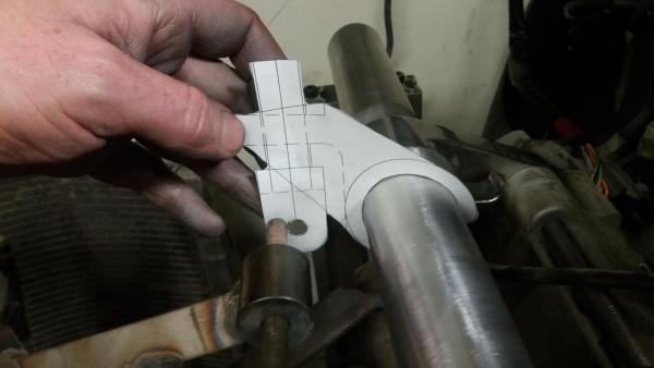
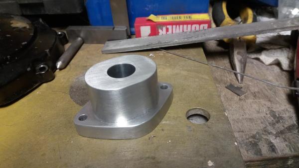
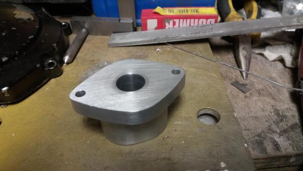
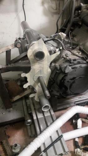
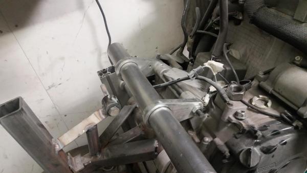
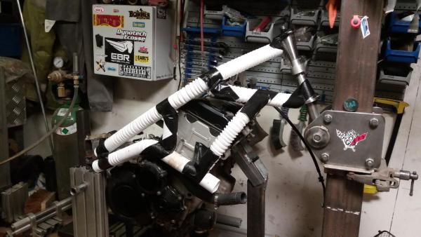
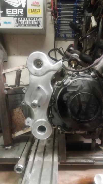
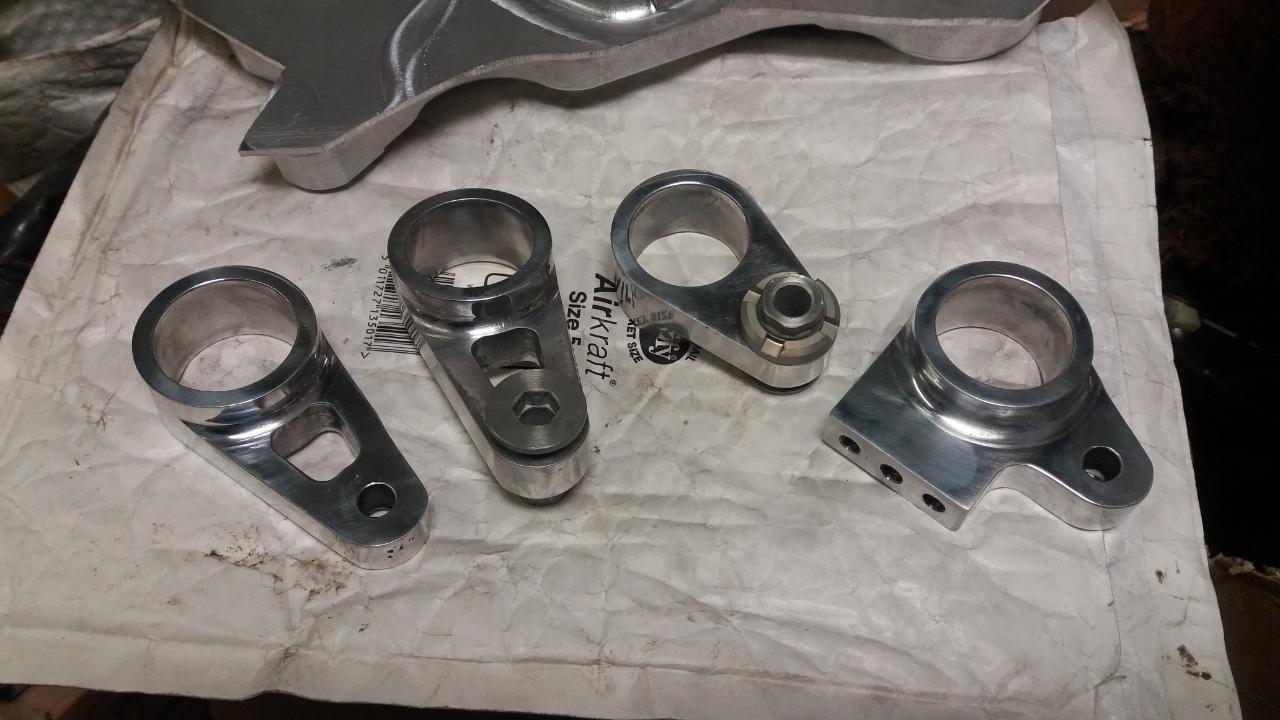
paper template lines up, knock up a polycarb version.... it fits too
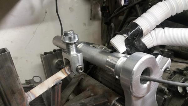
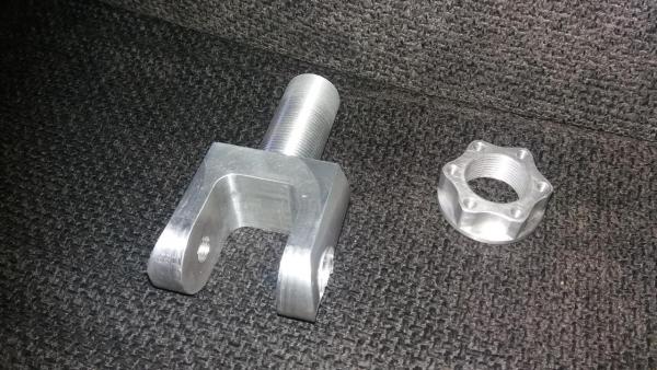
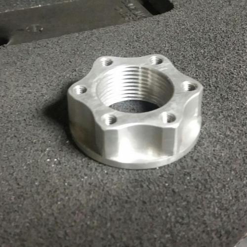
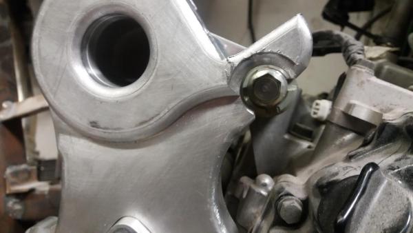
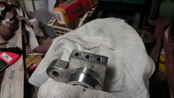
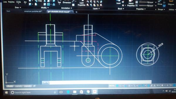
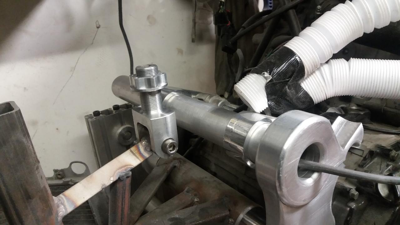
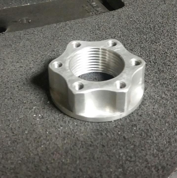
make up the shock mount fork next, the nut will tighten with a socket, as they do, then be locked in place with grub screws through the tapped holes (I take no credit for the threads, a young colleague is good enough to help out there)

-
 4
4
-
-
just noticed in the bottom pic, that lump sticking out the back is an exhaust hanger point
-
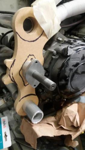
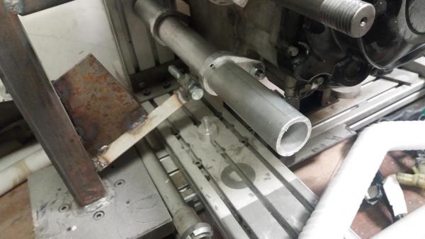
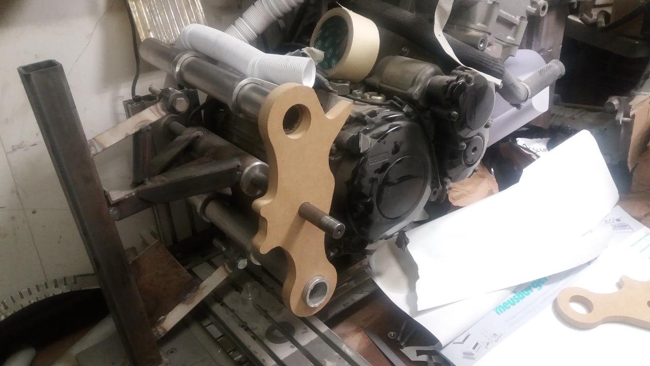
remake the MDF seahorse's in loominum and assemble them with the proper engine mounts, tubes cut to length etc. Had to notch one of the beaks or i'd never be able to get the top rear engine bolt in
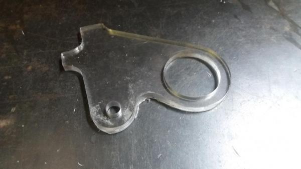
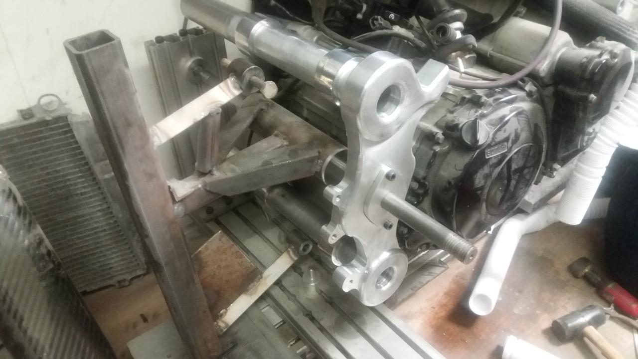
cut out a paper template 1:1 scale of the top shock mount , make sure it matches up with the jig


-
6
-
-
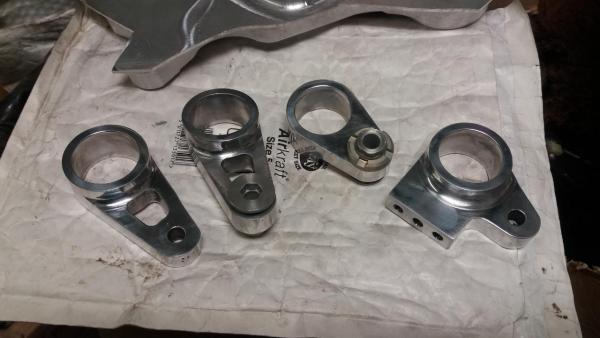
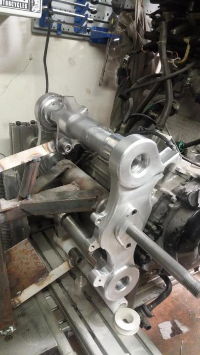
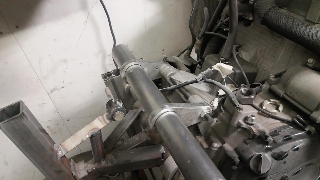
Decided to put the swingarm pivot in inserts, let me move it I need to, chances of that happening are slim.... but still
Rear engine mounts were good, so proper ones made up, used the little adjusters from the stock frame, seemed like a nice touch . The lower left hand side has a row of holes to mount a side stand to.
Started on a top shock mount design too, the adjustability in that is more likely to be used (hasn't been yet tho)
-
6
-
-
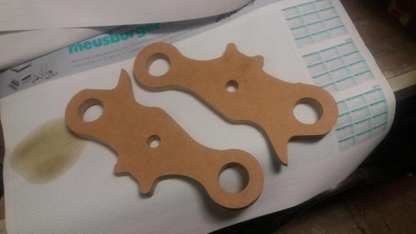
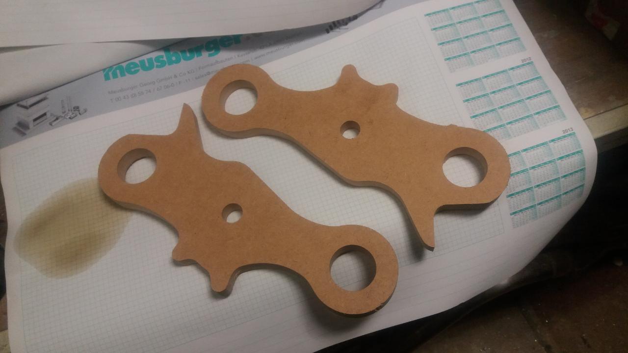
rear frame plates next, had to find a style that didn't look like any of the existing big tube frames.... ended up with something that, when viewed in isolation, bears a passing resemblance to a seahorse. Again I made an initial temporary set, firstly from card, then MDF , I like the through holes, they were kept

-
8
-
-
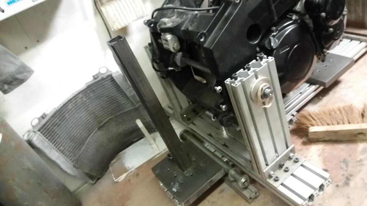
with that done it was time to make the rear mounts , I started of with a temporary set, no point going all in if they're going to be no use . The tube there is a bit heavy, but it's what I had and it was my first frame, later frames have been built from lighter stuff. Knocked up a headstock while I was at it
-
5
-
-
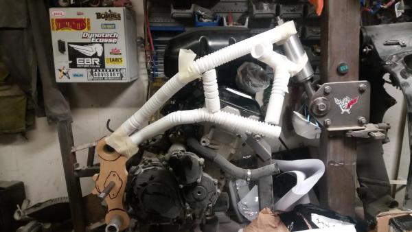
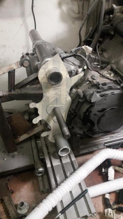
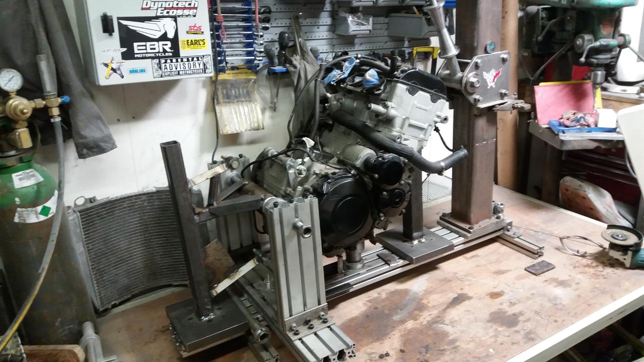
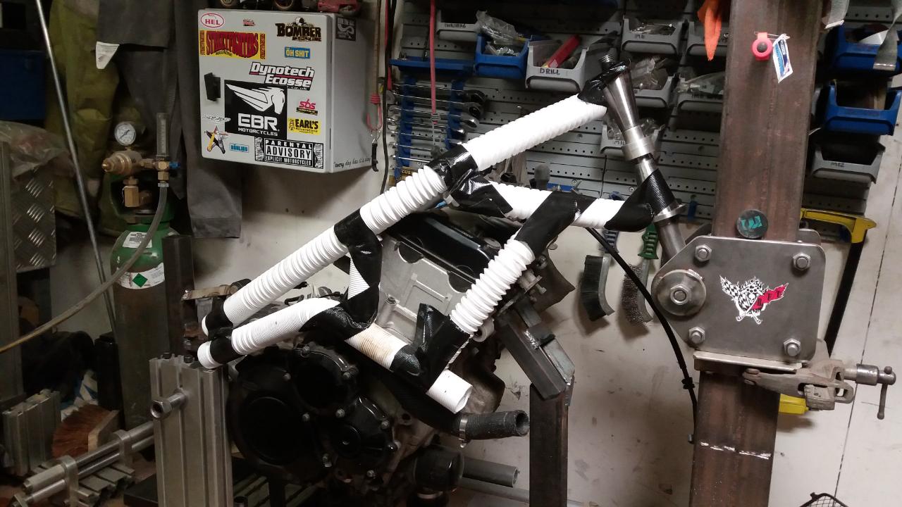
original frame was set up in the jig and the engine secured, letting me take it off and put it into storage until such times as the build was complete, I then bent up some flexi plumbing pipe, giving myself half an idea of what it would eventually look like

-
6
-
-
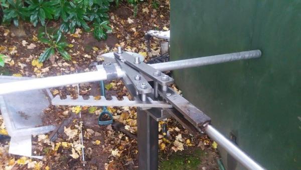
before starting this i made a JD style bender, a frame jig and a swingarm jig ,
(apologies if this thread seems a bit disjointed and lacks continuity, it's been a while. I have a build thread else where, but copying that seems a bit lazy, )
-
5
-
-
so quickly moving on, let me hopefully make it a little more palatable
It was at this point I did think to myself "WTF am i doing, that bike was mot'd ,run, sounded great.... a little work would have made it look pretty good....."

-
3
-
-
If your reading this I may have got away with it, The powerplant, while not new, isn't proper old, but I'm hoping the build it's self ticks some old skool boxes
Yes I make use of a CNC mill for some components, but they're all designed and made by me, but the bike was built by me , in a 12x8 garden shed
It is of course already finished and on the road, so this will be a what I did rather than what I'm doing....... trust me, you don't want to see what i'm building just now
so without further ado
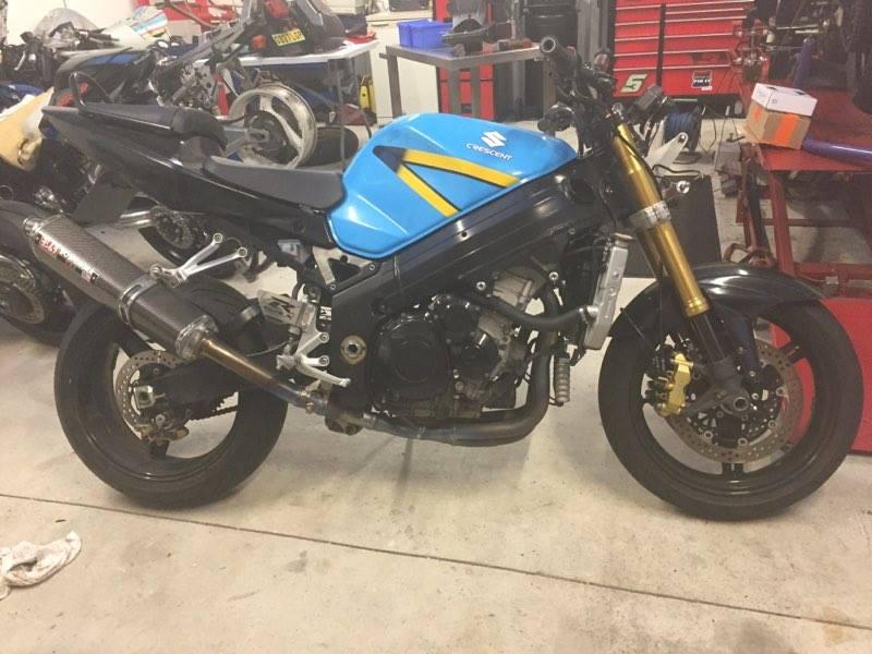
the chosen powerplant, still wrapped in an unacceptable 21st century guise

-
4
-
-
rules read, she's not getting in, ......... it's just not oldskool
-
2
-
-
35 minutes ago, clivegto said:
Looking good and from what I understand it's Suzuki friend is now welcome on site.
i'll go RTFR
-
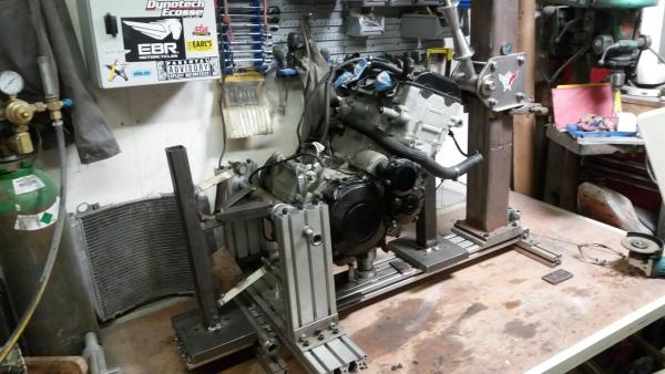
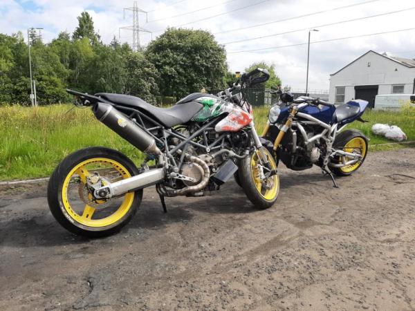
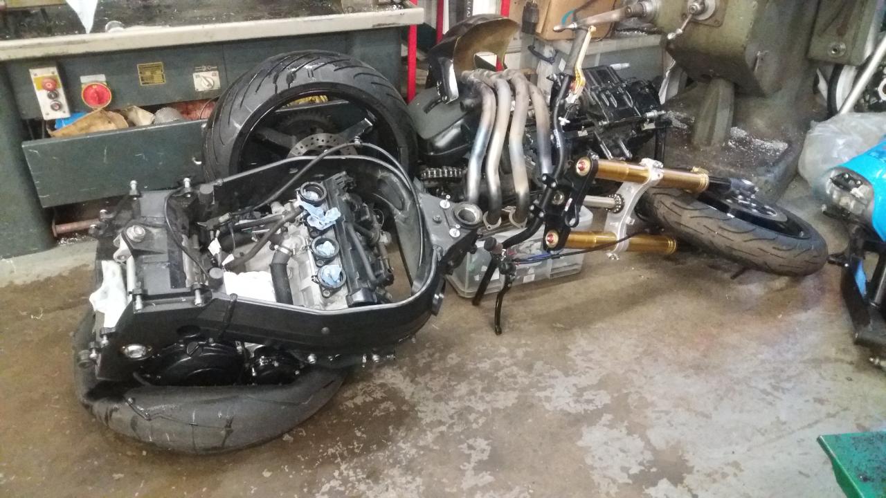
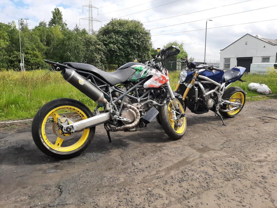
still not wired up, but it's out of the van it was living in after being evicted from the shed (please excuse it's Suzuki friend, it's not old enough to be here by its self only 17)
-
8
-
-
-
bearings may have settled and need adjusted (tightened)?
bearing deff tight in the seat, not catching on a step on the stem?
nut is clamping on bearing, not at the end of its thread?
-
1
-
-
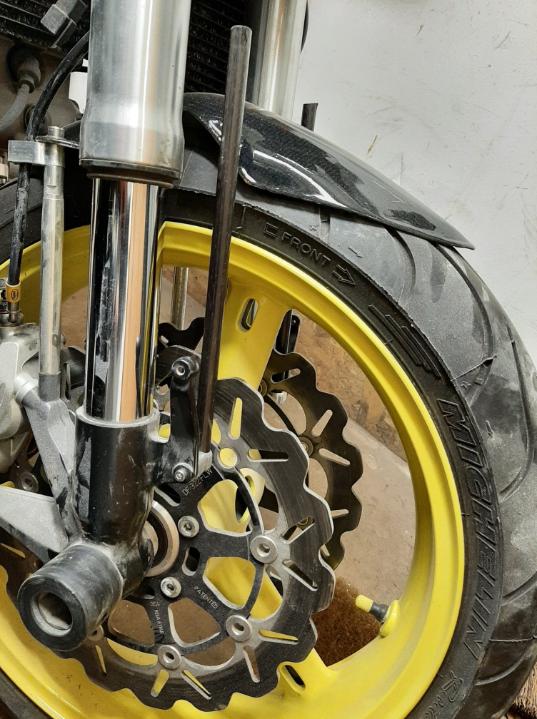
13 deg is a reasonable number, I'm sure someone will have a Katana they can measure
-
more ossumness from Meester Vizman
.thumb.jpg.40b958ff8f1b3cc68819b8de0da27a78.jpg)
-
10
-
-
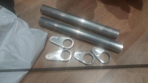
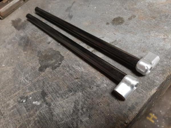
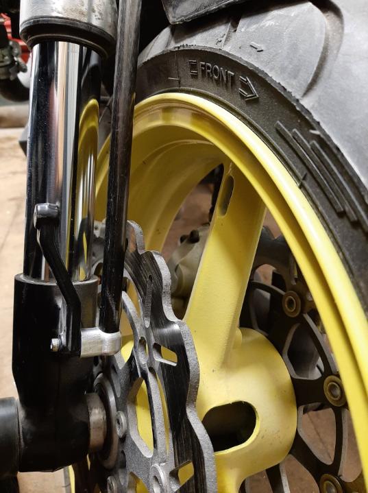
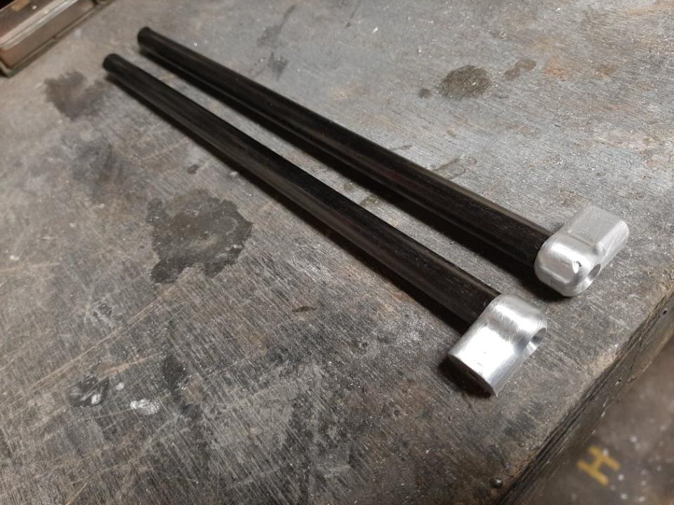
made a start to the front mounts, I don't want big muckle billet mounts so time to break out the 12mm carbon rod and make some fittings


-
4
-
-
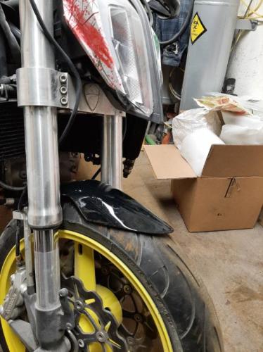
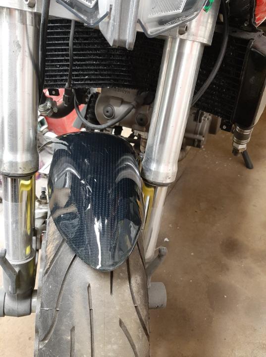
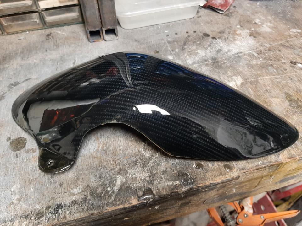
sprayed it with the shiny can , hung it on the forks , it'll need front mounts or it'll rip orf


-
3
-
-
Strangely enough I built my bike from an 03/04 GSXR , I only need to lose 3/4 of a stone for it to be ideal , closest thing on list
-
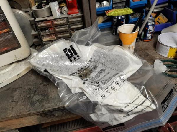
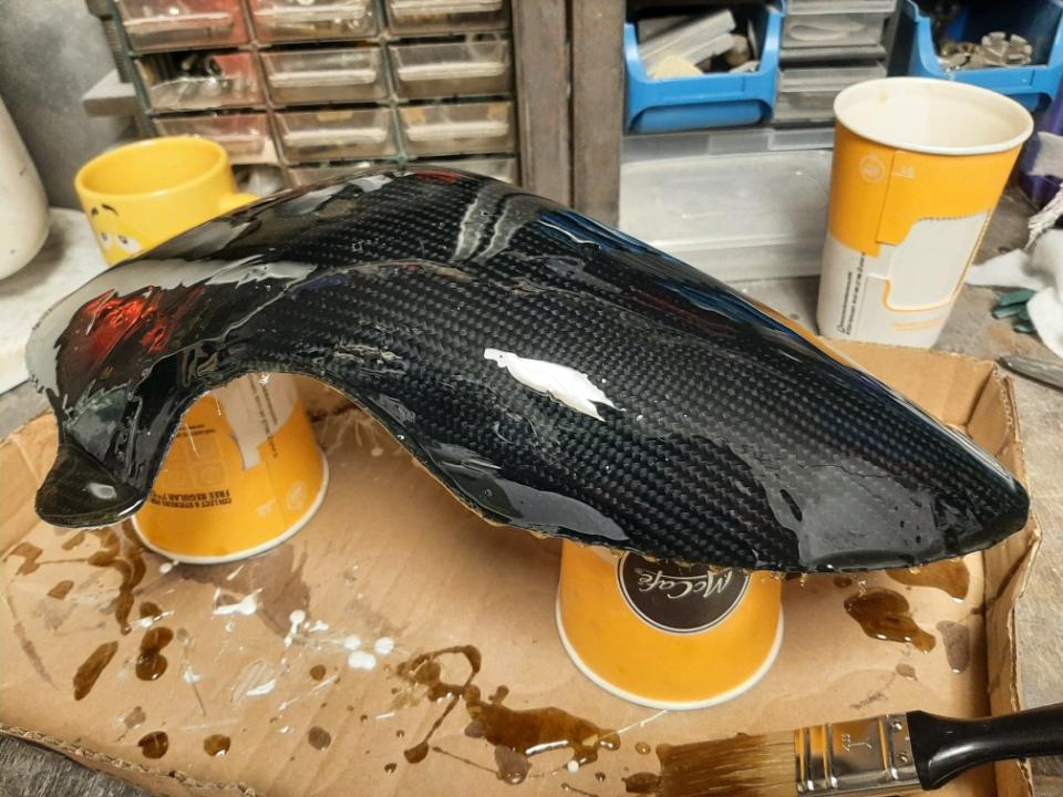
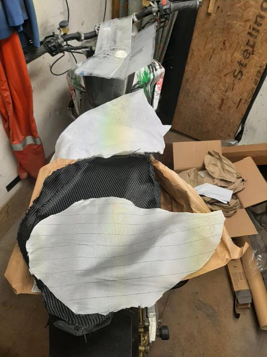
got the kevlar, peel ply and breather layer all cut out on Saturday ready for today. Up Sunday and off to the shed, mix up the resin and get it all loaded into a vacuum bag, never tried this before ... turned out ok, the mock up I cobbled together was the better part of 600g , vacuum moulded part about 150g. It did need a final cosmetic layer of resin brushed on, that'll need to wait until tomorrow to be rubbed down


-
4
-
-
7 hours ago, Swiss Toni said:
Remember ... chicks dig scars!
")
up to a point... my wife is getting fed up taking me to the hospital apparently

-
that'll leave a mark
 ,
,
-
coolio


.jpg.45e241ba9d31739d22ad22f8e1ffc7de.jpg)


pushing my luck
in Water Cooled, V-Twins, Singles and 2-strokes
Posted
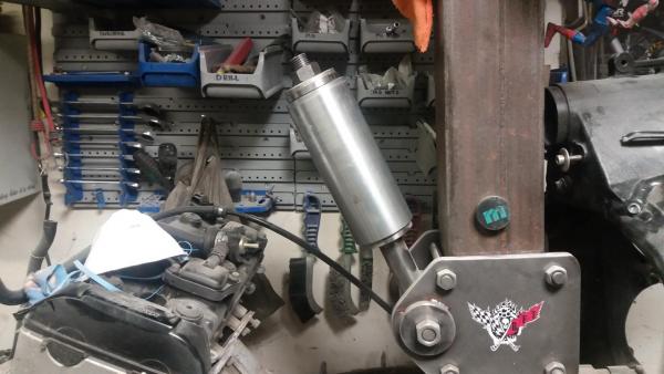
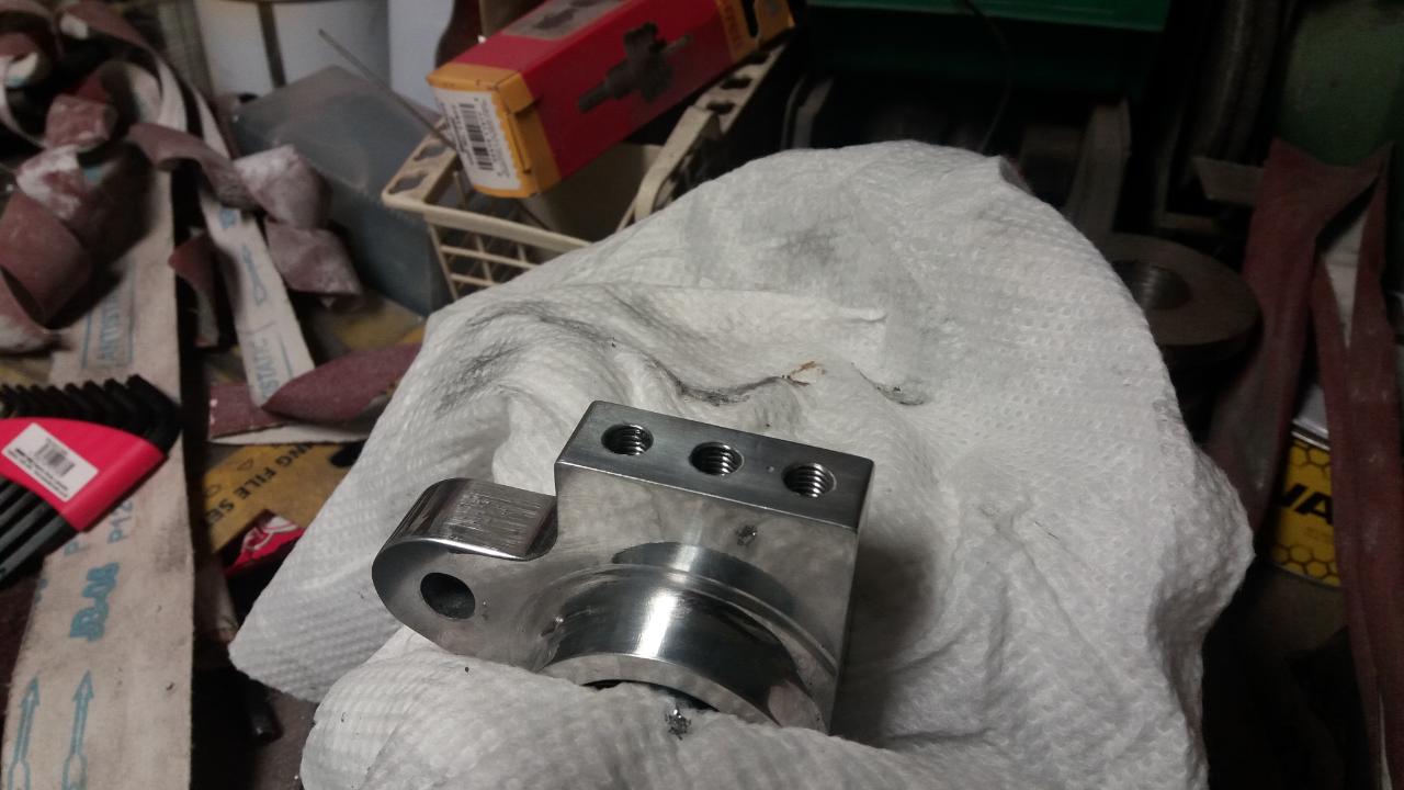
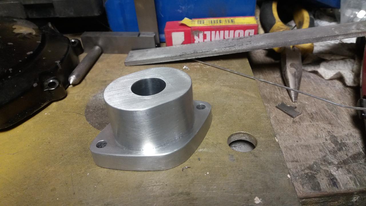
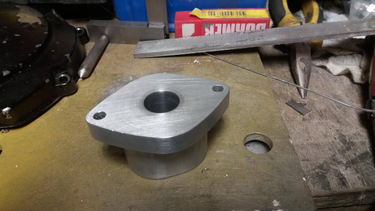
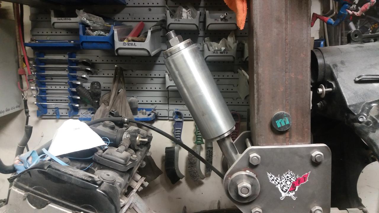
Rest of the top mount next, and a mount for the lower linkage. The donor bike had a 10mm spacer at the shock mount, so I done the same, to be honest it'd prob be better without it as its a bit twitchy (yes I could remove it, but i like how the tail sits)
top mount looked a bit bland, big expanse of flat aluminium, so I popped a pocket in it and added a bit of engraving, once built up it's not easily seen, but I know it's there, and that's enough for me