


Buzuki
-
Posts
180 -
Joined
-
Last visited
Content Type
Profiles
Forums
Events
Posts posted by Buzuki
-
-
10 hours ago, Duckndive said:
Just read that again on PC
Where does the "unfiltered oil" come from then
 and how does it remain that way
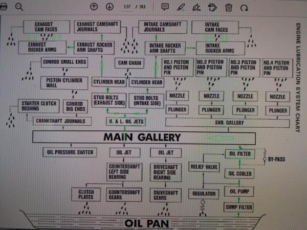
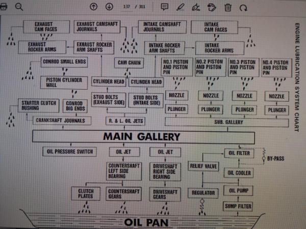
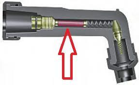
Unfiltered oil use the smaller oil pump , which basically sucks the oil from oil pan which is further distributed via two hoses up to the cylinder head cover , and further to 8 big oil jets which splash and cools thermally very loaded points on aluminium cyl.head , finally that but now heated oil falls down in the oil pan via on the engine front placed two big oil metal pipes and two stud bolts , that`s how oil head cooling circulation loop is done , btw, those from the front two oil metal big pipes have also the function as some sort of minor oil cooler , since majority from the cyl.head returning heated oil pass through them , it is important to notice that cyl.head oil cooling loop have almost no any oil presure but have very high rate of oil flow, if I remember correctly for very early slabby 750R engine that`s about 52L/min. at full engine load and at max. RPM , without this oil cooling system aluminium cyl.head will be melt down very quickly ,
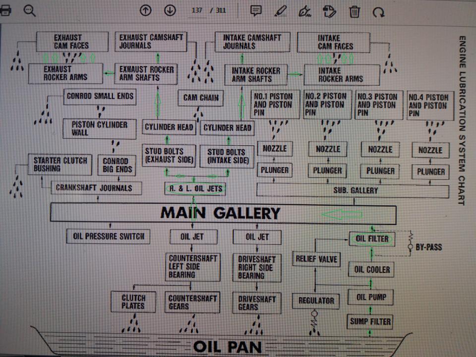
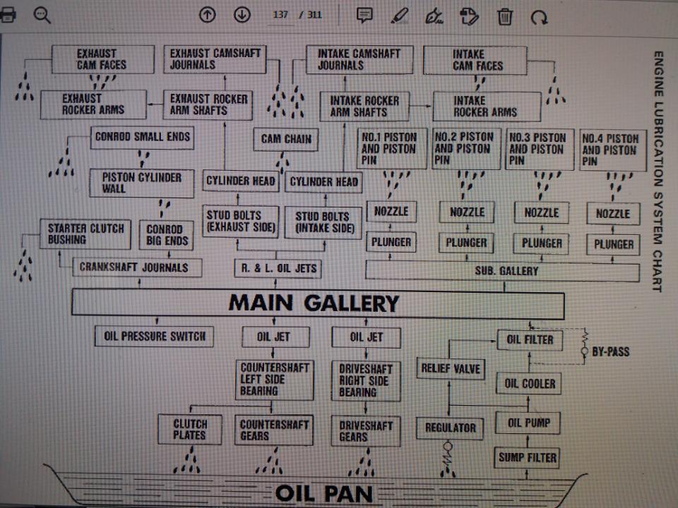
as for engine lubrication system there`s another bigger one oil pump which sucks the same unfiltered oil from the same oil pan , but now under pressure the oil goes to the Oil Filter patrone and further filtered then all the way to the camshaft assembly as drawn in this sketch ... just follow the green arrows ...
IMHO it is not good to mix those two functionally different oil circuits anywhere , since lubrication oil circuit is under pressure and uses filtered oil , on the other side is the cyl.head cooling oil circuit which work with very low oil presure and uses Unfiltered oil .
-
I would never connect those two separate oil circuits together,
1) for the simple reason that the engine head cooling oil circuit uses unfiltered oil , so that any dirt present in the oil can easily reach the rotating surfaces of the camshafts and can damage them significantly,
2) the oil pressures in those two separate systems are completely different, so any interaction between them can lead to problems, mainly problems with effective and good lubrication of the entire camshafts assembly,
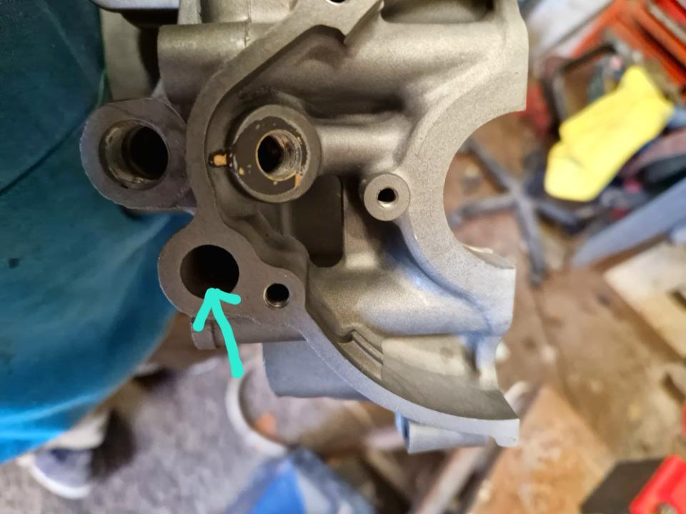
3) if you want to achieve better and more efficient lubrication of the entire camshafts assembly, then the only way is to slightly widen the original left and right oil nozzles located in the engine block, since internal hole diameter of this two oil nozzles directly determine distributed filetred lubrication oil volume to entire camshafts assembly . -
-
-
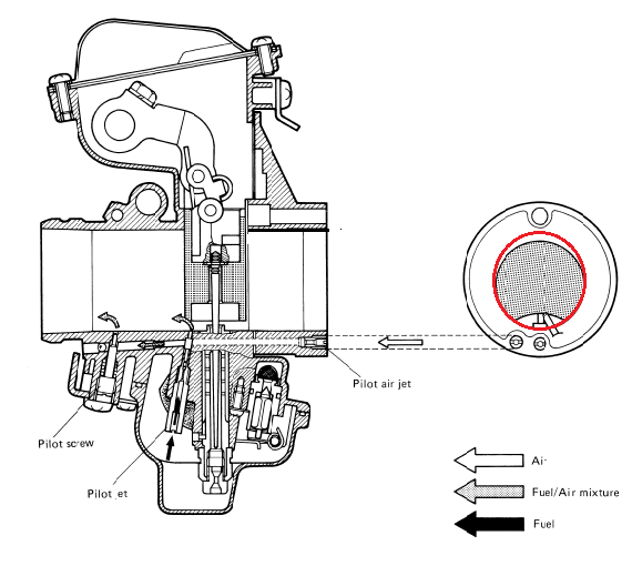
Long time ago I have the same problem with my 750 short stroke when I installed K&N RU2922 racing air filters , by changing standard #112,5 main jets with bigger #135 solved the problem , #37,5 pilot jets remained the same , all this on the standard Mikuni BST36SS carbs ,
btw , be very careful with that dedicated original K&N filter oil , that oil in contact with any rubber parts will have very negative effect causing rubber hardening .
-
 2
2
-
-
47 minutes ago, wraith said:
So, which to adjust, the needles or pilots?
As it's just on that part of the revs where they swap over. Or just try one then the other, which is my normal way

I'm thinking the needles, as it runs great below 3000 rpm and over 5000 rpm runs great
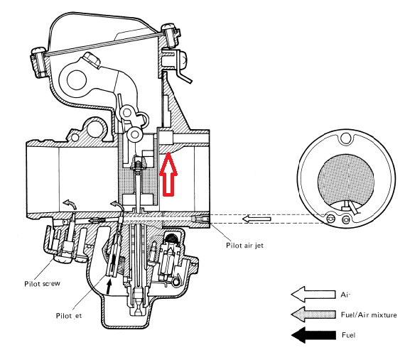
First Pilots and not needles , leave needles in the central groove , check the spark plugs faces color than play with bigger or smaller size of the pilot jets ,
any way also check for those O-rings condition which are hidden behind any carbs intake rubber boots , if those O-rings are bad false vacuum leaking can occur causing nonlinear gas (acceleration) response and uneven operation on idle gas .
-
1
-
-
After constant ride at 3,5-4000 rpm remove and visually check the faces of the spark plugs , if the faces are black and greasy than your carbs runs rich , and opposite if the spark plugs faces are dry and almost grey to white than your carbs runs lean .
-
1
-
-
4 hours ago, george 1100 said:
Maybe it became an issue so on the later 750, they re-engineered it. Every photo I've seen of 85_86 cases has a hole
I don`t think so , since oil sub gallery is directly connected to the oil main gallery , you can clearly see that from the engine lubrication system chart from the original Suzuki GSXR-750 (FGH) service manual ,where oil sub gallery is supplied with pressurized oil which serve for cooling of the engine pistons via four plunger and associated nozzles ,so good oil sealing both for left and right side is very important ,
btw ,later GSXR models both 750 & 1100 crankcases are redesigned and simplified and don`t have that oil sub-gallery any more , but only oil main gallery.
-
1
-
-
1 hour ago, Jpich85 said:
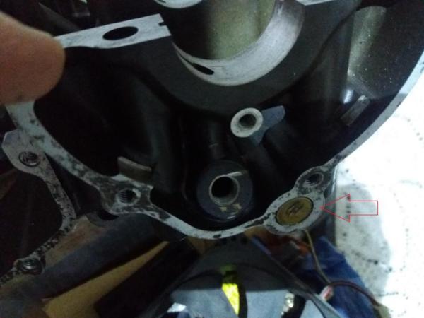
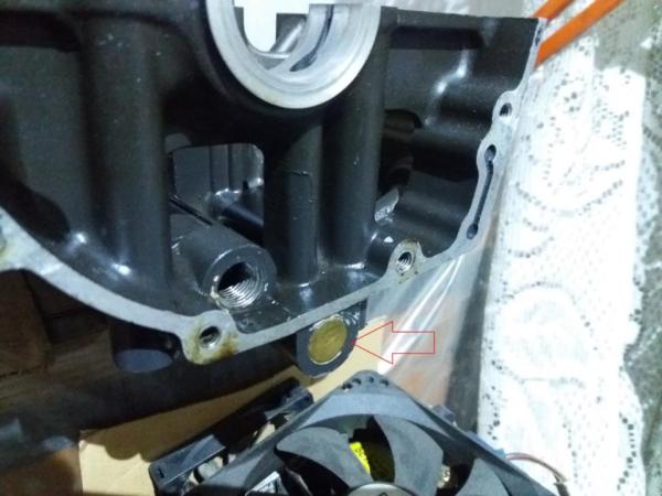
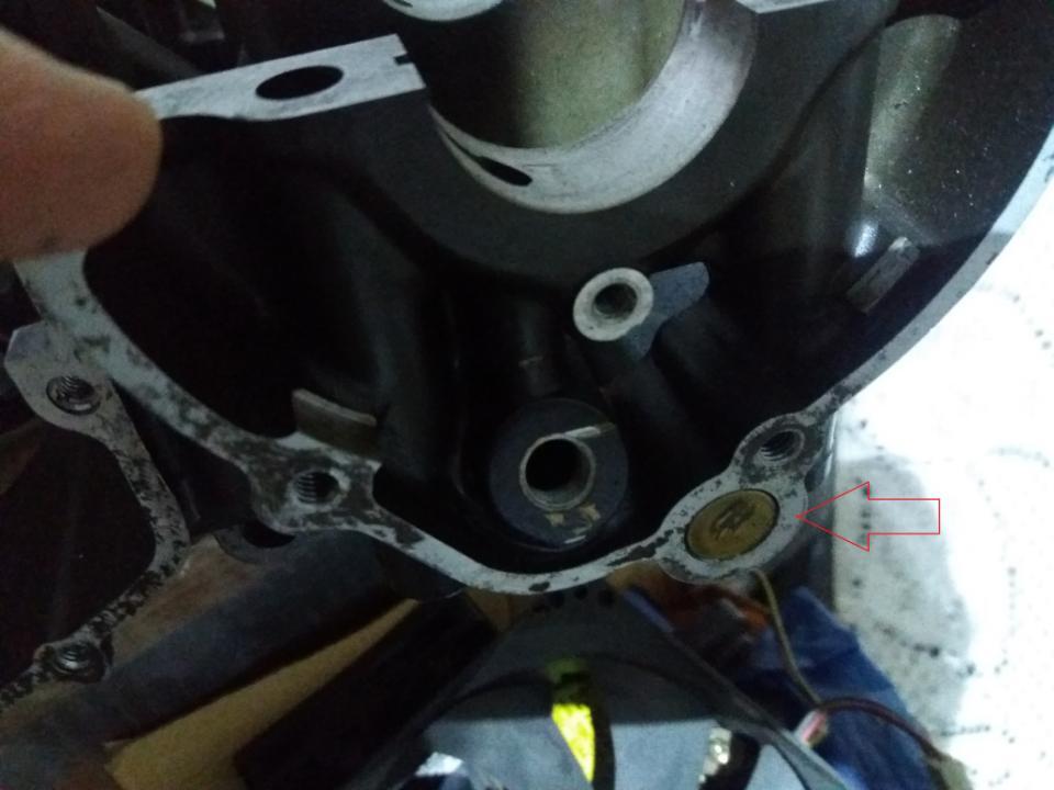
Thanks for the help mate, I would expect each side to have a brass plug but from I've researched on the early 750 engines I don't think they put a brass plug in on the ignition pick up side, seems strange but I think the ignition engine cover just blocked it off.
Without that small brass plug oil sub-gallery perfect oil sealing will be just impossible , ignition engine cover altogether with associated gasket have nothing in common with oil sealing role of the oil sub-gallery .
-
On 5/6/2023 at 11:26 PM, Jpich85 said:
I'm getting ready to rebuild the engine on my gsxr750 1985 and got the engine bits back from the cerakoters,
After giving them a clean I noticed this hole near where the ignition pick is, which gets covered by the engine case.
I'm pretty sure this is usually blocked off by a brass bung like it is on the other side and like I think I can remember from previous engines I've had but there's no sign of anything ever being in there and I can't see how it just fell out.
I've asked around and can't get a definite answer so thought I'd check with you guys.
I'm not sure if something had fallen out and I need to make a new brass bung for or if it was like that from factory and just leave as is?

On the each side of the lower engine block half is one brass plug , they have to be there and have to seat very tight and secured with some kind of the liquid bond ,
that`s from the reason because one brass plug close the oil main gallery end , and second one close the oil sub gallery end , both of these oil galleries are under full oil pressure so no oil leak is allowed ,
btw, to perfectly clean lower crankcase block half ( main oil gallery & oil sub-gallery) those two brass plugs and two plugs with thread must be removed mandatory !
-
Also I will check all spark plug caps , since sometime I have found that internal RFI protective resistor have been burned and destroyed , just replaced resistor with piece of solid copper wire of the same lenght and diameter as original resistor was solved the ignition problem ,
IMO & IME those internal RFI resistors actually is not needed if the spark plug is R-type , `R` stamp mean spark plug with internally integrated RFI resistor .
-
1
-
-
15 minutes ago, fatblokeonbandit said:
Camshafts and cylinder heads, depends how much power you want and how much money you have

GSXR 750j/k cams drop in and give a good boost of power with a race can and decent air filter, if you can find them
Thanks man !
Yes I have those J/K cams , same as nice race 4-2-1 exaust system altogether with K&N air filter .
-
14 minutes ago, fatblokeonbandit said:
BUT its very very easy to up the HP, using GSXR parts.
I`m interested so please explain me , usually which GSXR parts is best to use to up the power ?
-
Year 1998 , question : Where this Bandit engine is power restricted to 72KW / 98 HP ?
-on camshafts ?
-on carbs ?
-on CDI ?
-on exaust system ?
-on static compression ratio?
-or somewhere else ?
-
12 hours ago, Joseph said:
thats because the restrictor is welded into the headers at the entrance of the downpipes. there's no spare part to reference or show
1410040C04H01 general header part number for all markets 1991 1100
1410040C30 (E4) is the header part number for the french market restricted version with the welded pipes
example of a standard french ones here :
i misstated the carb restriction. it's the slides that need swapping or drilling the hole out that is there on full power bikes
")
Same welded headers restrictors was on my GSXR750J (88) series 4-2 exaust system , with restrictors engine power was limited to about 100HP , developing around 230-240Kmh max speed , after I grinding those extremely hard welded material and widening those holes internal diameter engine power rises , so the top speed was now about 265-275 Kmh , at intake side all elements remained untouched series, also I have noticed that engine was developed less heat , which is IMO one good side effect ,
but regardless those series headers pipes inner diameter still remained smaller in comparison with cylinder head exaust holes , so for really full open exaust system both inner diameters have to be with same dimension .
-
Jpich85
Measure piston outer diameter down by lower part of the skirt and also measure cylinder bore inner diameter upper close to cylinder head , than calculate the difference , piston to cylinder tolerance limit is 0,120mm , if your measured difference is inside of this 0,120 from factory limit you can reuse that piston and cylinder block again , just use some extra-fine tool to rectify and polish that piston surface scuffing and scratches , of course all others piston dimensions have to be carefully measured and checked , all that is already very well described and explained in original Suzuki service manual ,
btw , IME those Suzuki pistons are from the highest quality and over the time wear is minimum , so usually they can be reused again in combination with new piston rings set .
-
1
-
-
6 hours ago, davecara said:
Unless theyre damaged, you wont need to replace the carb rubbers themselves, just the O rings. Just be dead careful taking the JIS screws out that hold them on. Dont try and do it with a Phillips screwdriver as it'll cam out and damage the head of the screw
If you cant find the Lidl ones, you'll want 4 of 0928040020 from Suzuki. Theyre only about £4 a throw. might be a quid cheaper off Grumpys
O Ring(d:2.4,id:43.2) is the size btw
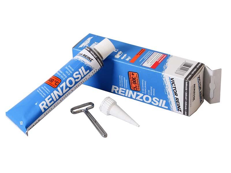
Many times I have successfully solved that chronic false vacuum leak because of those bad O-rings which is hidden behind each rubber boot just by adding layer of quality silicone kit over that flat surface where those O-ring seats , without to replace old ones , my favorite silicone kit is the high temperature Victor Reinz , typ Reinzosil 300 , it is fuel resistant and it is almost as some kind of rubber type of sealing kit which is also very resistant to high temperatures , it is ideal for that position ,
of course the best way to stop vacuum leak is to replace those bad four O-rings with quality new ones altogether using some quality silicone kit ,
and yes special care have to be paid when those eight JIS screws need to be removed , since aluminium cylinder head can be damaged very easy .

-
1
-
-
It is important that those four small rubber bungs (plugs) to stay in the original positions to seal against false fuel flow , but over the years and with those modern fuels they become hard and loose the original seal function , couple years ago I have successfully replaced them with precise machined four small brass plugs and that set of carburetors become again OK ,
for correct operation of your set of carburetors is also very important to check and replace all others rubber parts !, mainly O-rings .
-
1
-
-
17 hours ago, coombehouse said:
Gurls blouse did the low tension ring thing on 2008 blades too. Many drank oil, they modified the rings for 2009 onwards which fixed the problem.
Also not enough oil return holes number on the piston oil groove just behind the oil ring caused abnormal high oil consumption .
-
1
-
-
Les or more everything you need to know is explained in three page on these 10 Year old topic : https://www.say what now!?.com/threads/how-to-convert-vm29s-to-tm33s.323315/
-
1
-
-
Basically it`s not to complicated to machine those VM29SS carbs (but have to be very very careful !!!) , since you only need to re-bore only upper side of the inlet plate to about 32 - 33mm diameter , outlet side is already 33mm wide if I remember correctly ,
after this operation you have to play with slightly bigger main jet , and yes IMHO those VM flatside carbs bore widening have sense only if you have full open 4-1 race exaust system ,
btw , that first GSXR750 generation was from the factory limited to 100HP peak power on the exaust system pipes inner diameter and carbs inlet diameter (29mm) .


-
4
-
-
IMHO what is most important is that all four compression chambers have the same volume , so make simple test by pouring some diesel fuel or motor oil with calibrated syringe in all four comp.chamber , than notice and compare compression chambers volumes , if all four comp. chamber have the same volume than that cylinder head is OK .
-
-

Big Block Rocker Feed
in Oil Cooled
Posted · Edited by Buzuki
No ,bigger oil pump for high pressure engine lubrication loop directs oil flow through the Oil Filter Patrone , and that`s the Filtered oil ,
but second smaller oil pump for low pressure cyl.head cooling loop do not directs oil flow through the Oil Filter Patrone to be filtered ,
and that`s the whole difference .
ps, of course that both oil pumps takes the same unfiltered oil from the same oil pan.