


nlovien
-
Posts
622 -
Joined
-
Last visited
Content Type
Profiles
Forums
Events
Posts posted by nlovien
-
-
is there a fix if you consider - to remove the cam cover, maybe even fit the carbs - you got to remove the engine mounts and let the engine drop - not ideal - might need a bit of frame tweaking on the lower rear cross tube ( looks like the back of the engine would sit on this tube - you could cut out the middle so the engine drops through it and fit on offset engine mount / brace ) anyway - the idea being - not everything can be done or removed with the engine in situ but you don't have to fully remove the engine - i.e. a half way house
-
mind if you go EFI you should really also check / maybe upgrade your charging system / wiring and battery capacity - atleast note it, EFI can put a fair load on a system not designed for it
-
38mm Mikuni RS flatslides - could maybe give you that extra bit - dam't good excuse anyway to fit them
 - ps you really don't muck around - build a bike quicker than what it takes me to ponder over the next bit
 ")
-
2 hours ago, markfoggy said:
Scallop the arm. 3mm plate in there properly welded and you will lose next to no strength. IMO.
brill, thanks - right where i'm thinking - make a half tube with an ID a few mm larger than the shock spring diameter and - as you say - scallop it in
- got an added bonus in doing this
at the moment I tapped through the bottom plate of this brace to bolt up the mounts for the bellcrank tie rods - not happy with this as a final solution - was going to weld up once confirmed - but now I'm cutting into the box = I can put in an additional internal brace plate to achieve a decent bolt thread and spread this load = strong brace either side of the scallop
-
yir right - I mean prehistoric
 i'm stuck in a late 70's early 80s time warp-- your old bike looks familiar, i'm sure I was looking at pics of it a few weeks back, very neat - great to see it being properly used
-
great classic frame
, please let it mature into old age gracefully by keeping a sprinkle of old school in the build
-
thanks - got a fresh set of artyfarty eye's on it today and the other person pointed out the obvious that I didn't see - but now pointed out - I can't now miss it, the seat and frame tube line is driven by the Engine side case - take the average line through this case top 4 bolts and project it to the moulded line mid section on the seat - make the frame rail match this to join it together - bingo!, its almost where i'm at anyway, but didn't know why- in hindsight looks obvious - probably best seen by - what if these didn't line up - tried it - and it looks crap, all goes to proove, this 2nd person who spent 4 yrs at art college, obvious it wasn't a totally wasted education
")
-
more than welcome sir - a wee bit Northwest of Huntly - could use another set of eye's for this cosmetic stuff - its easy to stick a seat on her, dam't difficult to do this such that it looks right - some folks just have an eye for it - me? I need a mild stimulant to see it, problem is, once it wears off the next day - it's gone
- so what i'm seeing is - if you follow the blue scribble that could be the lower frame rail - at the same angle dictated by the centre seat line, the black bits are where I could cut out ( don't want the blended in tank to seat unit fit) and the angle of this cut could follow the frame top rail back -- but does it look right ?
-
 2
2
-
-
14 hours ago, grebo said:
Cant tell if you have a top shock mount sorted If not why not modify bottom shock mount moving holes forward to gain clearance in arm .
Couple of plate brackets and spacers to see if it works , then alter the mount you have
thanks - top mount is set - moving it doesn't really help - moving the bottom mount - this is my option 1 - i'd prefer not to move it any further as this will change the suspension ratio's - should have added, before I crashed the bike I spent a bit of time with Maxton getting the rear shock "tuned" to match the original rear suspension rate
Gammaboy - took a good look at this last night, there's plenty strength in this brace - recon i'm heading this way, even if I were to do a tony ( and that is a future option) I wouldn't know what rate or rate profile to go for - the bloomin manufacturer's can't agree on this - I'll go this route after I get bum on seat - so best I keep as near to as was to give a decent base line
thanks - your feedback does really help
-
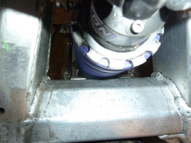
whats your thoughts on best solution for this ??? - i've cut out as much as can be ref: the swing arm cross member but i'm still not getting enough arm droop - needing another 5 deg s - what's my options
1) I can make another bell crank and move the shock mount another 10mm in to give more clearance - negative ? - that will be a 20 mm shift from the original harris bell crank - my ratios will be out to lunch, can review this using Mr Tony Foale program - it will tell me whats going to happen - not make it right - maybe we can find a workable bellcrank ratio
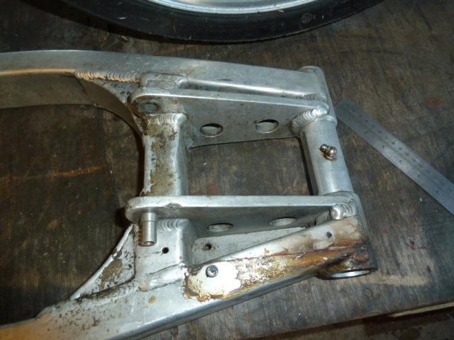
2) I can cut a portion out of the centre fwd face of the swing arm cross brace and weld in a recessed plate - seems to me there is plenty beef in this arms cross brace to enable me to do this - negative ? arm weaker - will it really make a difference ?? positive = I can revert to the bellcrank ratios Harris used
3) looking at the original Harris arm - note the two plates that brace the cross beam to the swing arm axle sleeve - i'm liking this, the load from the bellcrank tie rods goes to these plates - this would add back in some strength if I cut out a part of the cross beam between where I would weld in these plates
so my present directions is 2 with maybe 3 - but my reasoning is based on thought versus actual experience - easiest solution is 1 but my sense is my rear suspension could be bollocks due to wrong bellcrank ratios - do you agree with my logic ???
-
2
-
-
Well decision made ref: plates, tried a range of options for the top rear engine mount but the one that ticks the right boxes is to use the alloy plates. OK thats the engine mounts tacked up - x 3 I can adjust via removable plates - only the bottom rear is a direct fit so pretty easy to change the engine position if its not right - spent a lot of time drilling and bushing the holes in the engine and where the plates flange up - a lot of hassle because you then need to match drill everything - simple trick to achieving this is the make a centre point insert at each fit so when you offer up the matching bit - a wee tap on the insert finds the true matching centre for drilling, should be worth the effort, the overall fit is nice and tight - right - next is to fit the rear seat rails
-
1
-
-
22 hours ago, bluedog59 said:
Build your own.
but be clear that you will probably spend more achieving this if you compare apples with apples - big ££££ difference in building a heavy wall std alloy tube frame using MIG versus a lightweight thin wall chrome moly tube using TIG or gas rod - my cost for the Argon and specialist rods alone come to over £500 - add in approx £300 for the T45 tube, when they ask for £2K for a basic frame - your getting a bargain! - - you got to want to build one
-
1
-
-
if your looking for some serious bed time reading get his book on motorcycle chassis design - but if the only time yi seen the word trigonometry was on a scrabble board - best go freshen up on yir school maths
- also take a look at his suspension setup program - but be warned!!!! I think I was in a better place armed with ignorance, after reading his stuff, i'm still ignorant but now have a better appreciation of the questions to ask - now makes sorting out project bikes a bloomin nightmare "it fits, that,ll do = blissful ignorance versus it fits, but what about XYZ and the cosine of the vector force relative to the COG when accelerating at 1g over a hump back bridge ARGH!!!!! I jest - it is brilliant stuff
-
5
-
-
well known in European classic racing with a strong support based on CB / RSC engines - their frames are right up there with the best and one of the few that IMO have mastered the monoshock linkage - their nicest frames don't use a bell crank - direct link from swing arm to frame typically offset on one side so you get loads of room behind the engine / under the seat but the main point is you don't suffer from the sum of parts play you can get from a typical bell crank system - definitely one of the top frame builders that base their design on track experience
-
there's a range of things - all related to wear n tear that can be the root cause - and it shows up on cold start because this is when the fuel is least burn friendly - the good thing is anything you do to try and fix it is probably needing doing anyway, even if it doesn't sort the immediate symptom
you got the obvious fuel getting into and out of the right jets for cold start
you got a deteriorating ignition system leading to plug fouling
you got reduced vacuum draw - further complicated by changes to airbox / ex pipe
you got weeping valve stem seals - more common than appreciated - they go hard with the heat cycles = that slug of oil in the morning making the fuel even harder to light up
and you get a combination of all these and more, all playing a part - fix one and it helps get over the challenge, maybe not fix the cause though
kinda like ourselves - me I'm crap 1st thing in the morning - could be the extra dram I had or the lack of nicotine and caffeine in my system - two coffees and cigarettes and I start to wake up - but I know this isn't fixing the cause
-
great looking bike and as noted with the biggest search light i've seen -- could be the pictures but it looks like the rake angle has been steepened up ?? - are you using eccentric bearings ?
-
in my limited knowledge, raising the roof on the inlets for most of the older generation engines is a good thing - especially on 4 valve heads - huge subject that requires expert knowledge versus opinion but my stab at an explanation is
1) helps to unmask more of the valve circumference and reduces the negative impact of the turn into the valve pocket on the port low side = better flow
2) helps to promote tumble down into the bore - this tumble down works on 4 valve heads whereas swirl around the valve and across the head works on 2 valve motors
this is internet warrior info versus hard earned experience, so it could be fake news
-
1
-
-
very nice
- look's like there should be some nice stuff inside the engine
-
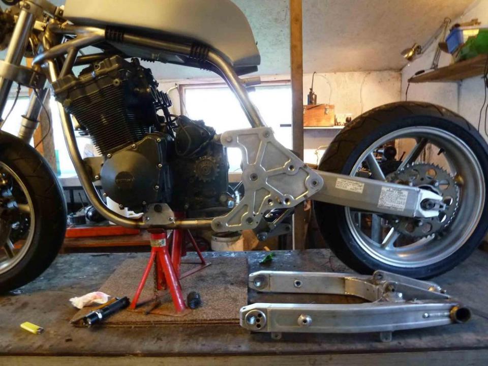
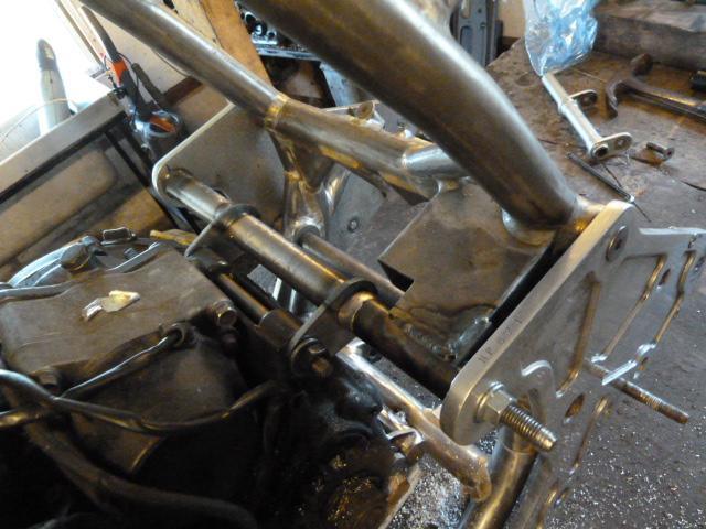
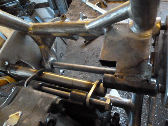
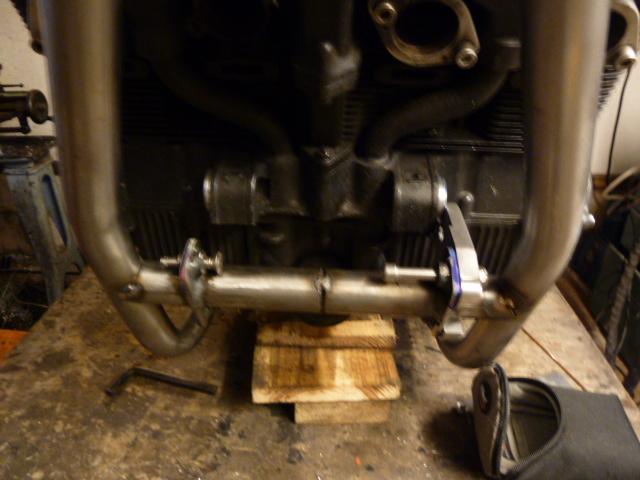
great picture - taking what looks like the 38mm tops are almost flush with the cam cover as a guide, quick check and i'm fine for 36mm carbs but going to have frame clash with the 38's - this could turn out to be the reason to port the std L head versus fit a dot one - or stick with the 36mm carbs, funny how decisions can be sorted by not so initially obvious things - thanks

aha! even better idea, so if you're looking for that reason to go bag a set of 38mm mikuni FS smoothbores - this is it
they will fit no bother - and they come with sloped carb tops as an added adv.
-
1
-
-
great thanks this helps
-
They were quoted as being M1R forks but TBh I don't know - they look like a 38mm marzocchi fork that you would find on typical Italian bikes around late 80's - no external adjusters, anyway i'll be cleaning them up and checking them out before putting up for sale
Agree ref: the CMA - they were period correct for P&M's - the story I got was nothing to do with any technical value - simply P&M were friendly with the guy along the block who made them and they got a good deal - hayho, the original mag alloy set I acquired lasted about 2 months on the road - amazed a wheel could make such a big crack and not disintegrate - lucky!, bin - replaced with their alloy road version - but now replaced with a set of classic dymags - 2nd fiddle to Astralites forsure,but a heck of improvement on the CMA
-
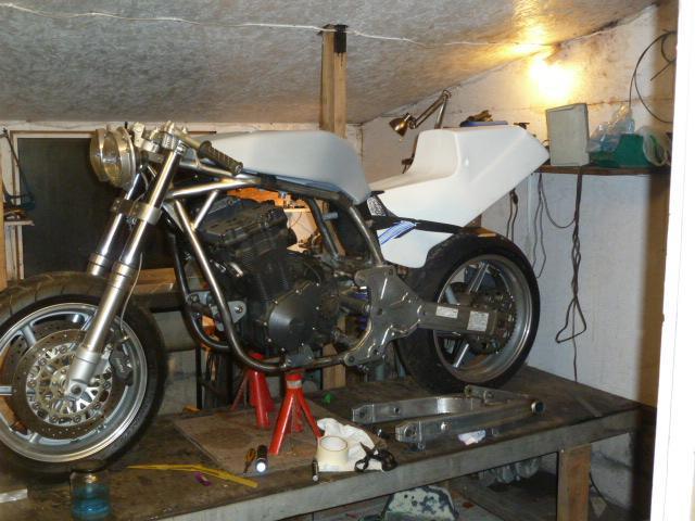
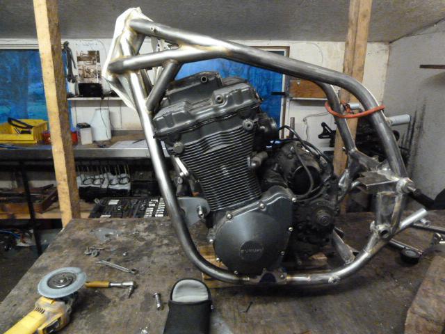
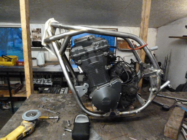
right i've been spending too much time juggling with engine position - got of the fence and fixed on a location - yi got to ride it to find out - mentioned in a previous post my hassle has been - got too much room to play with, so too many options
Started by making x 5 sets for the front lower mount - the 5 plates varied in height and fore / aft mount position so with this + the ability to pivot the engine on this mount I've got a compromise that ticks most of the box's
1) cam cover can come off
2) ex pipe can clear the frame downtubes (just!) whilst I can also make the 1st turn without too long a run from the head
3) carb fits without hitting the back of the top rails
4) engine weight is as fwd as practical can be + the crank height is in the right ball park
5) The sprocket axis to swing arm pivot is looking like the anti squat should be tunable in the right way
The negative is the sprocket it too far from the swing arm pivot - for me == the least negative consequence
the pics show how much adjustment just by pivoting on a set of lower mounts is available - its the fwd pitch i've gone for, benefit for it is - it brings the header nearer the frame whilst it raises the sprocket to improve potential anti squat - also pitches the weight of the head fwd - actually achieved more carb clearance aswell - added icing
knocked up a set of alloy solid bush's for the front then bolt up alloy plate to the cross brace - can now go align the rear mounts - nice to be moving fwd again

-
1
-
-
On 26/11/2016 at 6:02 PM, nightrider said:
good to know.
Building a 1100h track bike w/ 1157 motor this winter.
I have the option of BT36, BT38 & VM33 in my shed.
in agreement ref: BT36 versus VM33 - both good carbs but there is something about the BT36 that just works, very forgiving - best production bike carb I've tinkered with
-
1
-
-
nice find

another carb question
in Oil Cooled
Posted
use the mikuni HS40 manual as yir guide - bloomin good doc. - ref: the bit about fine tuning the idle / primary circuit - bigger fuel jet or smaller air jet maybe of interest
http://www.mikuni.com/pdf/hs40_manual.pdf