


NotStock
-
Posts
161 -
Joined
-
Last visited
Content Type
Profiles
Forums
Events
Posts posted by NotStock
-
-
I am not 100% convinced that my turbo is high enough to properly drain into my sump under gravity. It might be, but I won't know until I get the bike full of oil and at its final stance. I can't move the turbo, so I am contemplating a sump and scavenge pump.
I have two questions - does anyone know of mechanical pumps still out on the market? I have done a ton of searching, but I only come up with dry sump car systems (extra massive overkill) or references to pumps that seem to be defunct (emtes for example). If anyone knows of a good mechanical pump, please fill me in because I am getting nowhere. Second question is do I need sump or tank or whatever? I have noticed a lot of guys just running the -10 turbo drain line straight into an electric or mech pump. I like the simplicity of this setup, but I worry about not having a vent on the line between the turbo and the pump. In my mind you want the turbo to drain to atmosphere and have the scavenge pump pulling from a vented tank. I hope I am wrong, because I hate the idea of a bunch of unnecessary parts!
-
The more I look at these pictures, the more I like how tight everything fits. The plenum is right on top of the carbs/TBs and looks really tidy. I don't have room for the big gap you get with silicone joiners so this will work great.
-
Amazing! Thanks everyone. Should have asked earlier... I have been thinking about this for a while.
BTW, that fabricated charge pipe and plenum is nuts! Really cool setup.
-
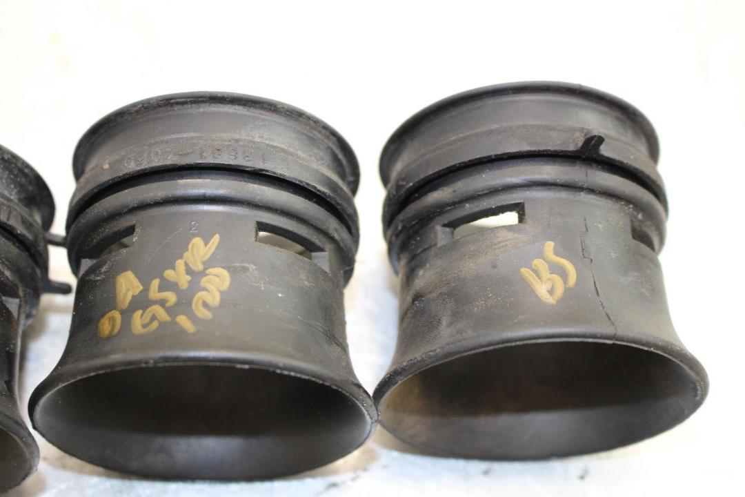
Anyone using stock intake boots as adapters from throttle bodies to a plenum?

This groove where they mount to a stock air box is pretty well perfect for the 1/8" material I would like to use to build my plenum.
Only concern is if they will seal against the sheet metal by only using this ridge, or if I will have problems with boost leaks. I will use some supports to keep the plenum from blowing off. Maybe there is away to glue them in for added security?
Just wondering if anyone had done it this way. Seems like an easy, clean, and low profile solution. Other options are to use silicone coolers or machine some adapters with an internal o-ring to fit over the TBs. Only thing that worries me about the o-ring idea is that everything will need to be bang on, like within a few .001" or else there will be fitment issues. Not so easy with a welded part and no mill...
The stock boots are nicer than silicone joiners since I wouldn't lose the space needed to add a spigot to the plenum and won't need a million hose clamps in there cluttering things up. Anyway, just looking for some input.
Thanks!
-
On 2/24/2019 at 12:59 AM, Gixer1460 said:
Not trying to muddy the waters but a swirl pot is usually fed by separate low pressure pump and has pot over flow back to main tank. The fuel rail return is usually back to the pot. The reasoning is the continual circulation of fresh cool fuel. Whilst this system is more used in cars having tanks susceptible to surge from cornering it could be applied to a bike. One thing - a vent from the pot to the main tank would help as you can't flow liquid into a closed container (rapidly) if the air can't get out!
Wouldn't returning to the main tank make more sense? Send the hot fuel that has been through the pump and FPR back to the main tank and let the pot be replenished with the lower temp fuel from the main tank? The main tank could act as a bit of a radiator and heat sink. I am completely guessing, no experience here, but isn't the idea to keep as much heat away from the pump as possible?
-
-
Like where this is headed. Nice work, and nice looking shop.
-
Moved this over to the project section. No need to clog up air cooled with what turned into a build.
-
One province over. I'm in NB. Shop is in the two car attached to my house. My problem is that I travel a lot, like 2-3 weeks a month, so finding shop time is hard for different reasons. Must say though, it is nice to be able to pop out and do an hour of work whenever I can fit it in.
-
 1
1
-
-
16 hours ago, no class said:
Coming along nice !
Thanks! Your build thread is good inspiration. Makes me want to get out in the shop and work on this pile.
-
1
-
-
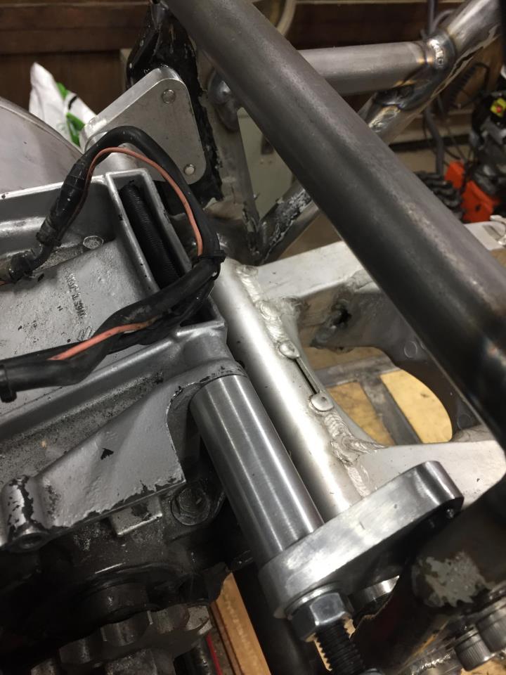
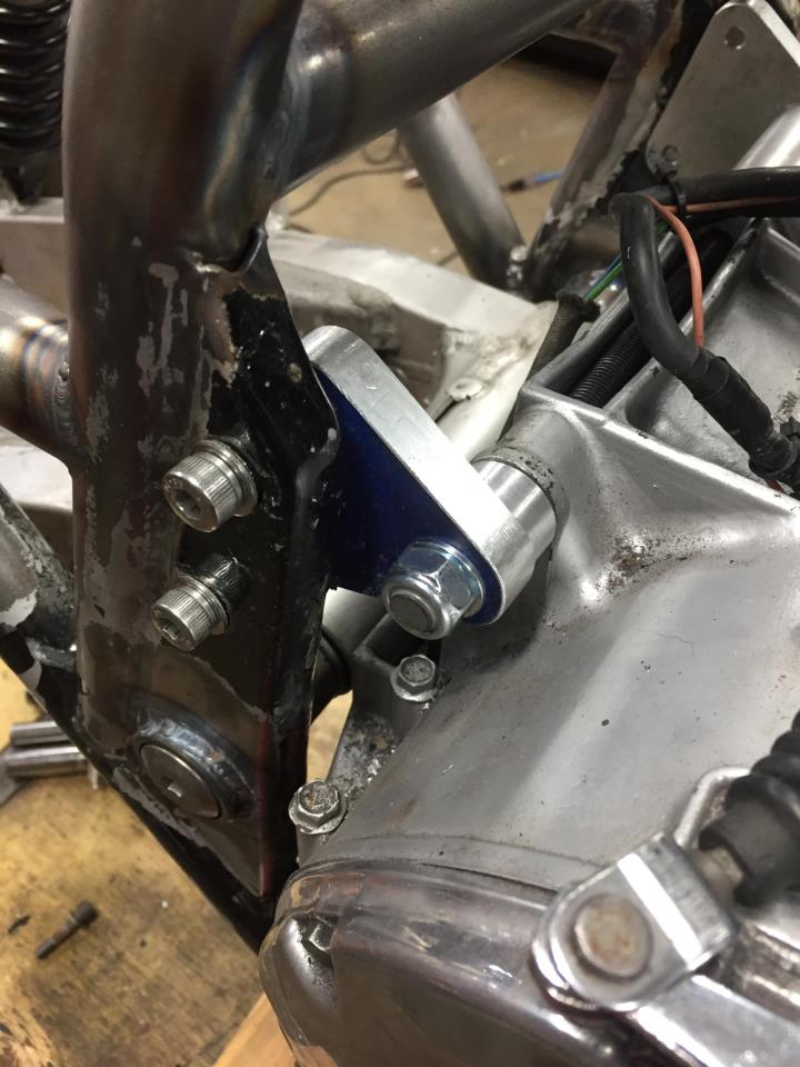
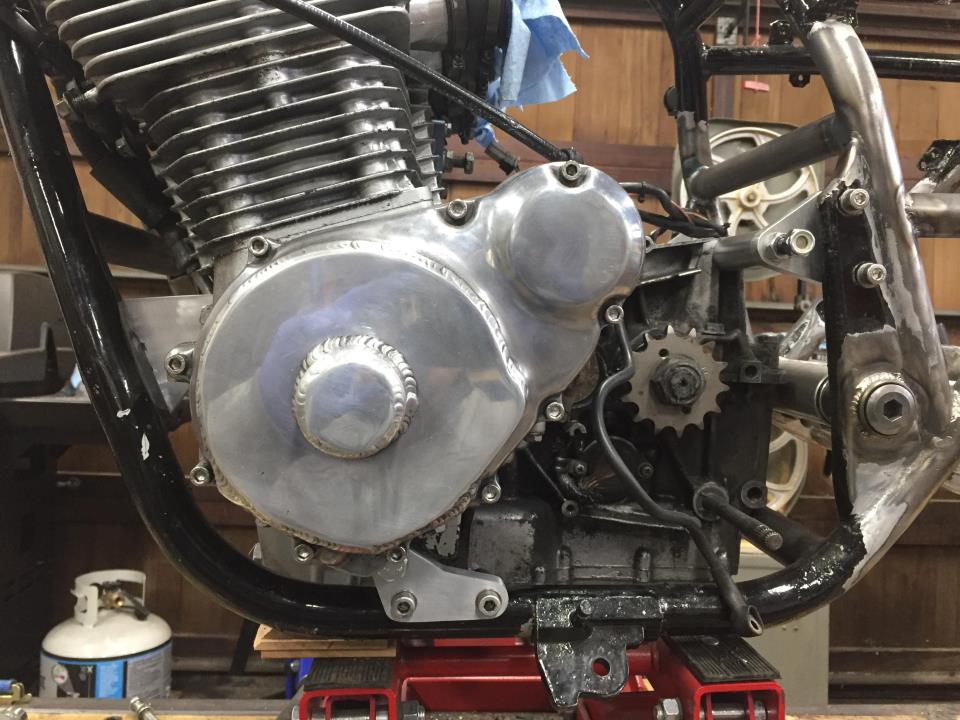
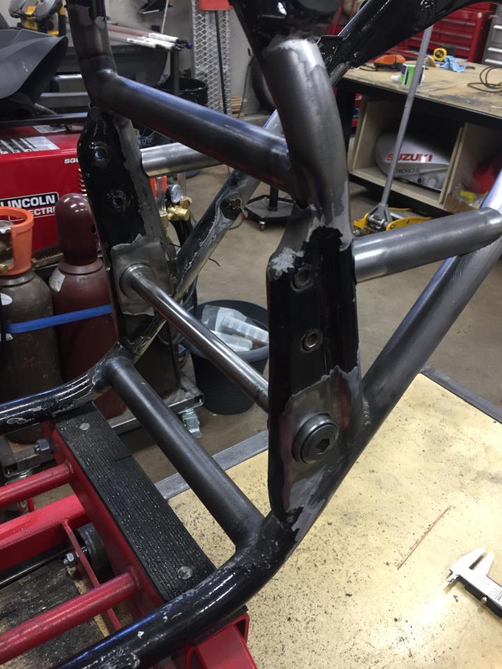
Motor mounts done. I moved the efe up a little in the frame to get better clearance at the lower mount. Maybe 1/8 of an inch.


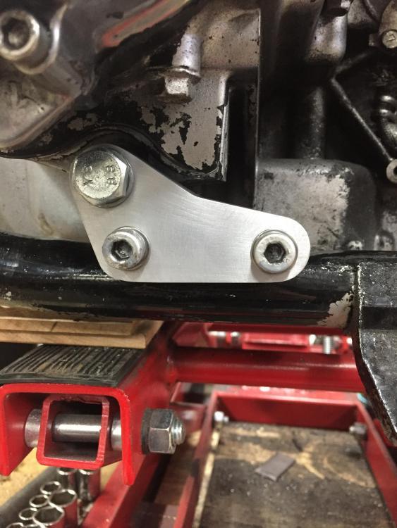
The front worked out really nicely. With the wider frame I could use straight 1/4" plates.
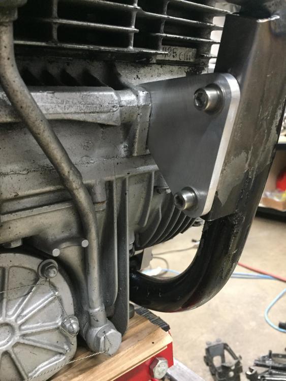
It was an iterative process. I made several versions that ended up in the scrap bin. Very happy with the end result, but the whole process made me really aware of how much I need a Bridgeport.

The mounts might get speed holes in the future, but not until I can do a nice job of it. I still need to weld in the fixed mounting points. But that is easy now that the motor is located.
-
3
-
-
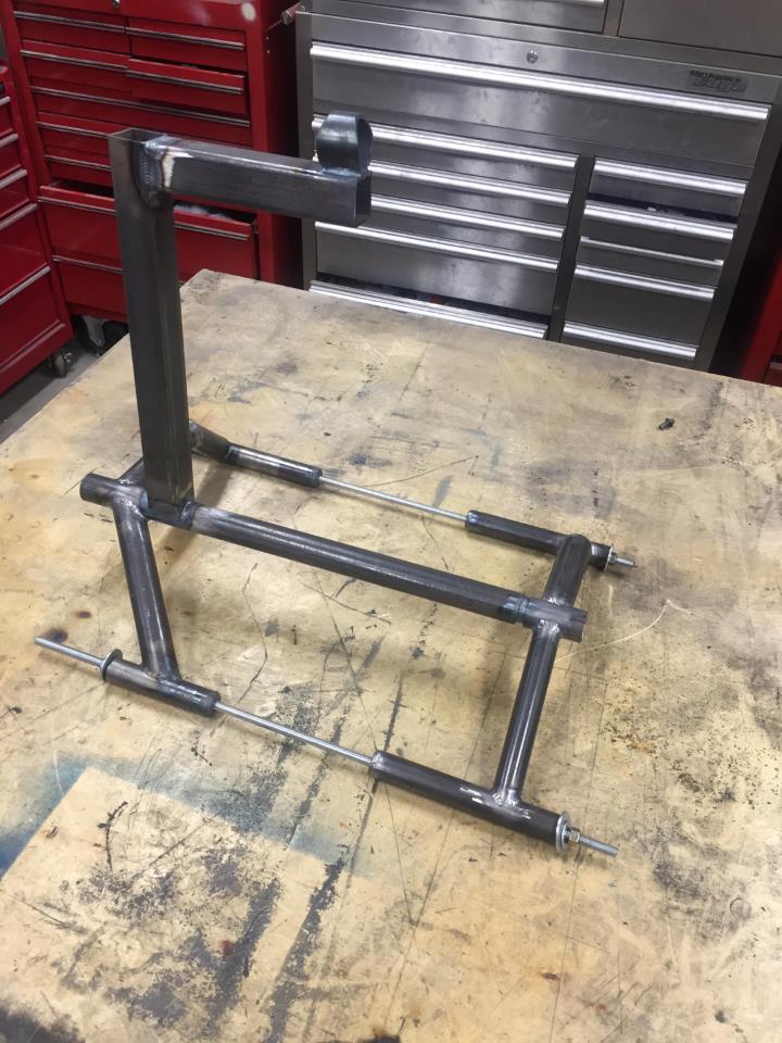
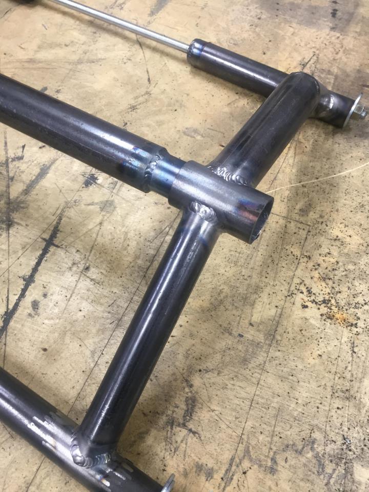
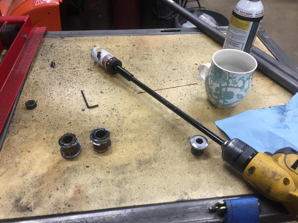
here are a few more pictures of the cradle and the way it comes apart to take the motor out.


Im going to move the hanging point back further to get a better angle of dangle. First iteration was a wild guess. If you wanted to run a piece of stock parallel to the backbone you could use an engine leveler.
-
1
-
-
On 2016-12-16 at 9:34 PM, busa1300 said:
Once the engine was out, I wanted to soda blast it and get it back to fresh aluminum. Repaint the top end. Then pull all the covers and polish them back up like new, and check the bottom and top end before I put everything back on with new bolts
I didn't want to repost the picture, but you did a beautiful job on soda blasting the motor!!
Would you be able to post some info on how you blast a motor without pulling it apart? I have been wanting to do this for a long time but I have never seen a good post describing the process. I finally have a compressor with the balls to run a blaster and I have a motor with a crappy paint job just begging for the treatment! Would love to see some pics or a description of how you go about it and get such good results.
Thanks!!
-
1
-
-
2 hours ago, no class said:
..... did you measure the I.D of the holesaw before you turned the frame insert ? Anyways.... not to worry .
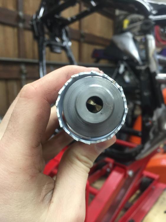
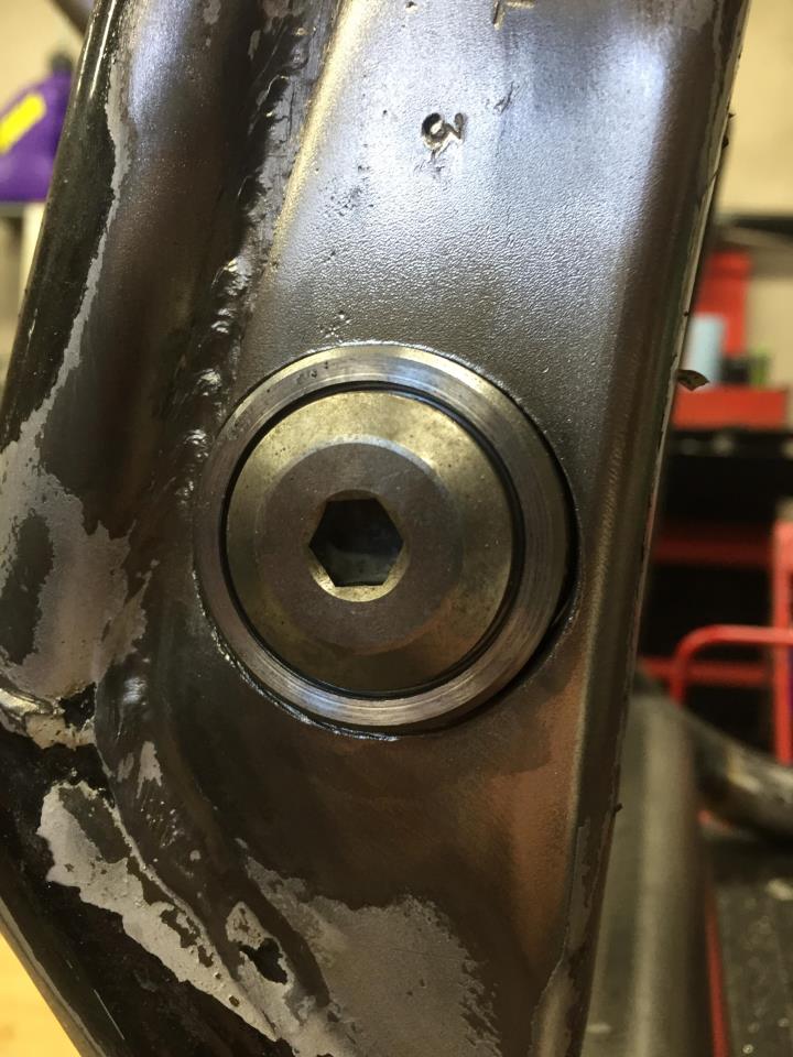
Well, hard to make excuses, but I assumed the flange diameter didn't matter. I chucked up an 1 1/4 piece of material to make the guide, assuming that the drill in the centre would be enough to guide the saw. In reality, I should have made the guide the same OD as the saw ID to keep it true to the drill bit. I never would have guessed that there would be so much runout in a hole saw setup. Ultimately, I got a lot of the runout out by messing with the arbor and the holes measured (shockingly) less than .005" oversize, so good result in the end. The saw was tight on the inner bushings, so Im sure those are perfectly on centre.
Hindsight, make the busing OD the same as the saw ID!
-
1
-
-
The quest continues...
Before anyone says "this is an exact copy of what no class did on his bike". Yes. Yes it is. There is not one original thought here, right down to the zrx pivot bolt! Thanks again, no class.
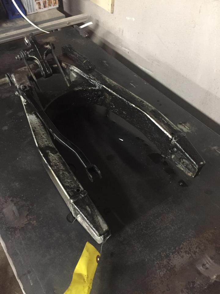
Built a bushing to cut the pivot out of the frame.
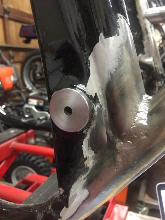
Naturally, after buying what I thought was the best hole saw I could get my hands on, and a fancy 3/8 arbor....
its super effing crooked and crappy looking. I ended up messing with it and getting some of the runout out of the whole setup, but it still had a good wobble. Note to self, order Lenox next time...

Metal chips and PB Blaster in my coffee, but the holes are cut. Get a 1/2" hole saw and a 12" extension. No class mentions this in his build. An 18" extension won't fit!
whipped up some bushings in the lathe and...


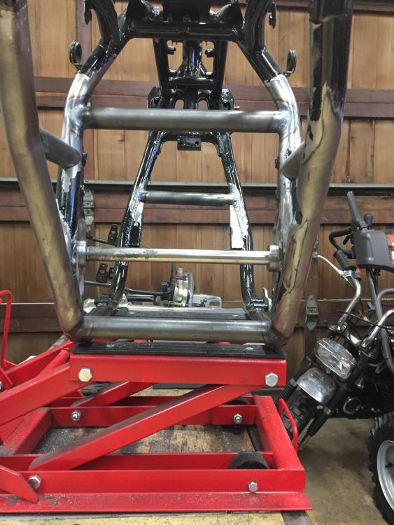
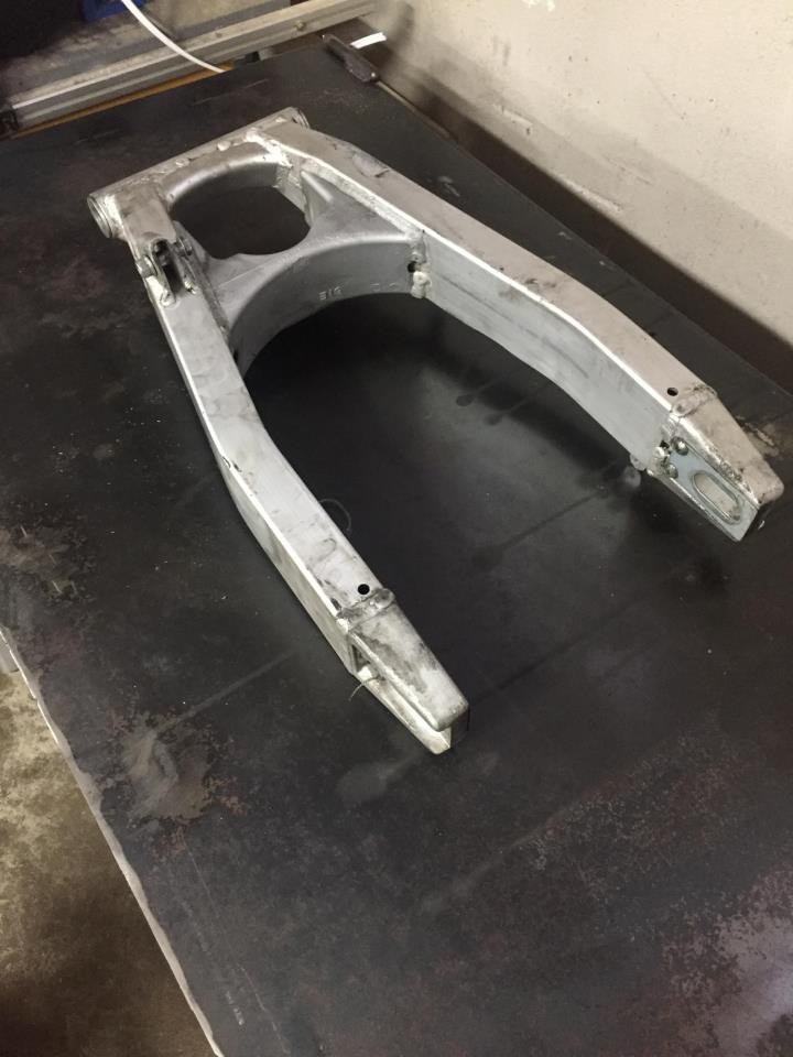
Ready for measurements and welding. Next up, swingarm install and spacers to finally get around to that problem of squaring the ass end up. God, did that ever snowball out of control.
-
6
-
-
Wow, very nice work. Tons of trick stuff and a really pretty end result!
-
Those bikes are the reason I'm all stressed out about swingarm length. They are running (from my measurements) 20" long swingarms. Looks like the b12 is 21" at its shortest. A bit long, but certainly better and lighter than the 22" arm I was planning to use.
Since I didn't get a stock kat swingarm with my bike, anyone know the approximate length from pivot point to axle? I believe the bikes you posted pictures of are running braced stock swingarms.
Since I have no idea how to make decisions on wheelbase and rake I decided to just copy track bikes. After measuring up pictures of old race bikes and the 1135r (from pictures in cad), they all seem to share some dimensions. Makes me think I'm on the right track.
-
On 2018-02-05 at 6:29 PM, no class said:
Yam thunderace has a beefy looking short swinger.... can't give ya the actual measurent though ..... btw.... good response on the frame spreding.... could not have said it any better myself .
No Class, any thoughts on lowering the swingarm pivot point while I'm in the process of making new bushings?? I was thinking of boring the bushings eccentric by a bit to move the pivot point down. Know what I mean? My thinking was to provide a bit more chain clearance on top of the pivot point when raising the back of the bike up. I would have to completely reassemble the bike and check the chain run to know if this is a good idea, so I'm just feeling it out right now. Maybe I would just be better off to make a slider for the top of the arm and not worry about it.
-
23 hours ago, SiBag said:
This was a quick mockup with the XJR swinger in a GS1000 frame.
(Yes I know the shocks are the wrong was round)...

I like that swinger a lot. Looks like the bandit one, but has dual shock mounts already welded on. I have a real fear of structural aluminum welding so it is a big point in favour of that arm. The chain adjusters on that arm are also cool looking.
I have a lot of good options now thanks to this thread and some conversations with members here. I find half the problem is knowing what is out there! I'm going to get the bike on its feet, set the rake, ground clearance to see what the shock mounts, swinger angle, and chain run look like before buying more stuff!
Also, good call on the shock disclaimer. The internet is full of people who are easily triggered, so its always good practice to disarm them right off the start lol. Bike looks cool! I was always a Z1 and H2 guy, but this Kat (and OSS in general) have me wanting a GS1000 now!
-
7 hours ago, SiBag said:
I was putting a XJR 1200 swingarm in my GS1000. Pivot point needs machining down but its doable.
Quite chunky looking.
I really like the xjr swingarm, and I have pivot room for it, but I'm worried it's too long for what I'm after. How long is that swinger from pivot to axle?
I bought the cheapest b12 swinger on Eblag and I think I might even take an inch out of it. Looks easy enough. Maybe not. I may just put it in the corner for my Z and buy something else for this project.
Check out the before and after on this greasy mess.


This guy didn't mess around when it came to chain lubrication. That thing spent a long time in my home brew parts washer.
-
1
-
-
16 minutes ago, gsx said:
Just curious and maybe missing something but how did you make sure the spread was even ?
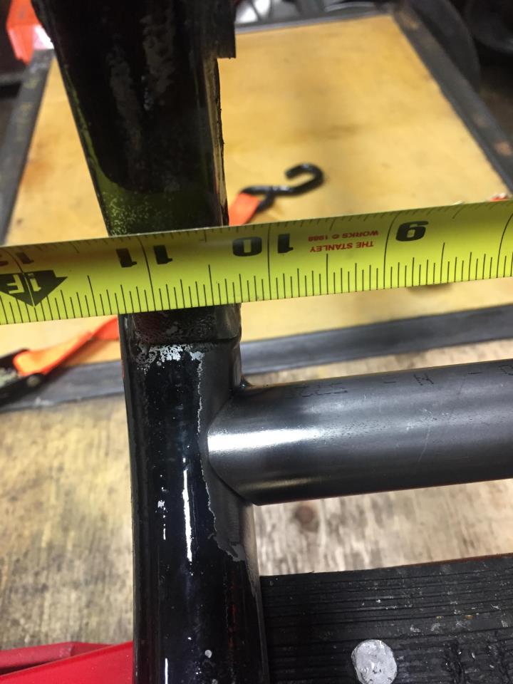
Thats a good question, and I had the same thought before shoving the jack in there. First thing (in my case only) was to finish weld the repaired side to make 100% sure both sides were equally stiff. After that, you don't really get any guarantees. Aside from making a serious jig, or putting it on a straightener, I don't see any way to ensure both sides are perfectly offset from the centre.
The good news is there is no reason for it to want to spread one side more than the other assuming your frame is in OK condition. Pushing against both sides when spreading the rails should keep everything even, both sides see the exact same force. When I squared everything back up and welded the last brace in, the pivot bolt didn't bind in the the existing bushings, which is a good indicator that everything stayed pretty parallel.
If you had something go south and one side spread more than the other, you could make adjustments in the motor mount spacers I suppose. It might even be beneficial to spread the chain side a bit more? In my experience messing around with a bent frame, it is REALLY difficult to find tiny misalignments in your frame in your home shop, so I doubt you'd be able to notice if one side spread a 1/16th of an inch more than the other. At the end f the day, we are only talking about 3/8" per side.
-
5
-
-
That pivot bolt leads me to my next problem... I still have not 110% selected a swinger. I have a shortened early gsxr one that came with the bike. I decided I didn't like it. Then I got a teapot swinger that I decided was too heavy. I now have a cheap bandit swinger, but I'm not entirely sure if it is the one for me. I'm practicing aluminum welds daily to get to a point where I'm comfortable modifying an aluminum swinger.
All I know for sure is that I want to run dual shocks. Open to suggestions.
-
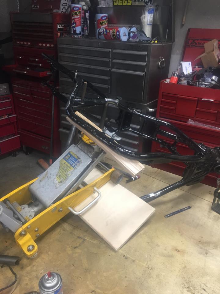
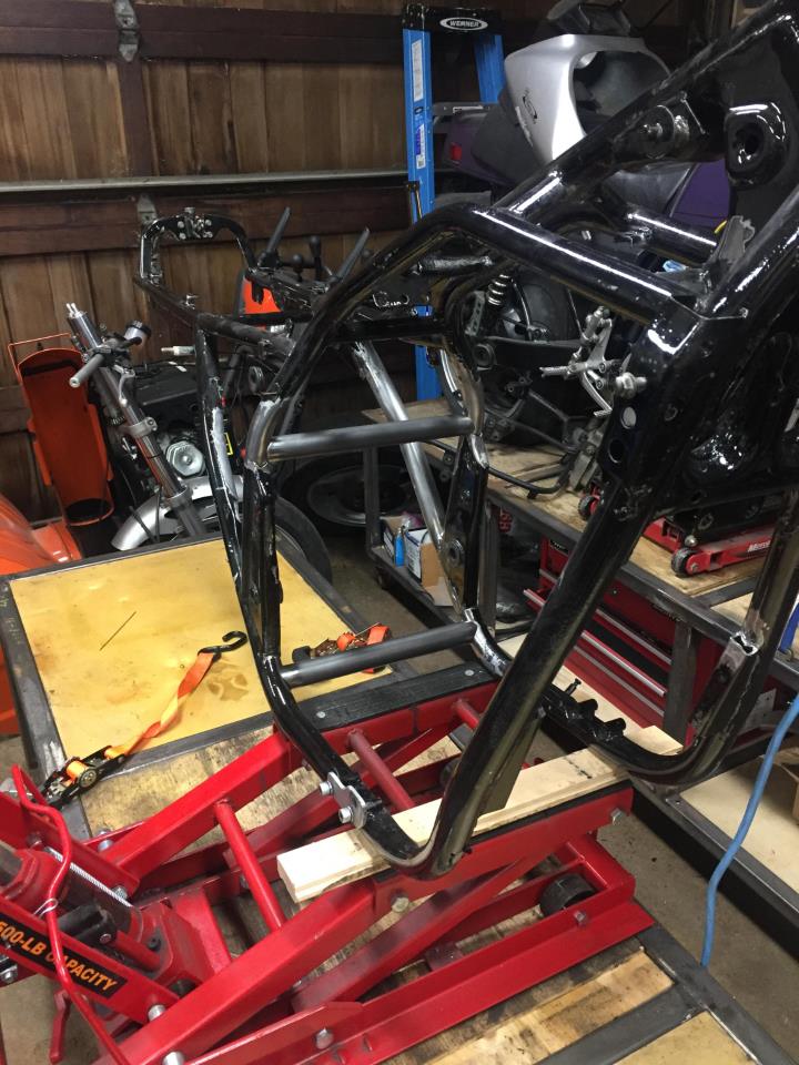
Well that was absolutely terrifying. Stress level is at 11 when twisting your frame up like a pretzel. I tried some really questionable setups with ratchet straps before resulting to the mess shown below. End of the day, it all worked out, just had to jam a floor jack in there...


3/4" doesn't sound like much, but it was well worth the effort.

Big thanks, yet again, to No Class for the instructions.
-
1
-
-
3 hours ago, SiBag said:
Loving the engine cradle. That is a rely nice idea.
I may just have to steal that idea for myself.
If you want to build one, don't make the same mistake as me, move the lifting point back further. My next modification for this one will be a piece of tube running parallel to the back bone on top. That way I can use an engine leveler to tilt the motor. If I had placed the lifting point further back it would have been better. I took a guess and missed by a little bit.


Turbo drain sump
in Forced Induction
Posted
Awesome! Thanks