Crass
-
Posts
256 -
Joined
-
Last visited
Content Type
Profiles
Forums
Events
Everything posted by Crass
-
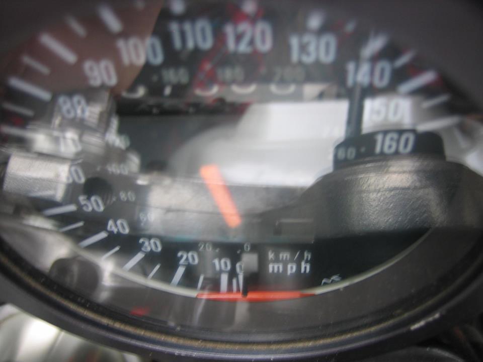
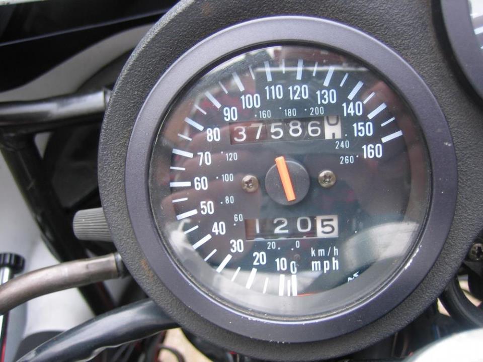
As you can see in the picture below there is a sort of shard of plastic left on the broken needle. This isn't off the front of the needle, must be off the back. So there's actually quite a lot of adhesive surface there to attempt gluing it together again. So, at the risk of having one of CC's 'fuck-this-shit' moments I'll give that a go using Loctite All Plastics superglue, which is supposed to be the dog's. Interestingly, the needle doesn't seem to be bonded to the mounting disc where it has snapped, so another bit of glue underneath there for strength might help. Anyway, I'll give it a go in the interests of economy.
-
Thanks for all this chaps, I'll take the clocks off and do all of the above and hopefully get a good permanent repair
-
Can you actually buy the rubbers? Looking at the online fiche it appears that the surround comes complete with the metal bracket, at a rather large price 34950-17C80. Or am I thinking about the wrong part?
-
Righto thanks, I can get in it to effect repairs then. I'll do what you suggest CC and replace the rubbers as well, otherwise I'm wasting my time. I might try gluing it. If that fails does anyone know if the needle pulls off? I mean, I guess it will but is it supposed to? I don't want to pull it off and find I've wrecked it.
-
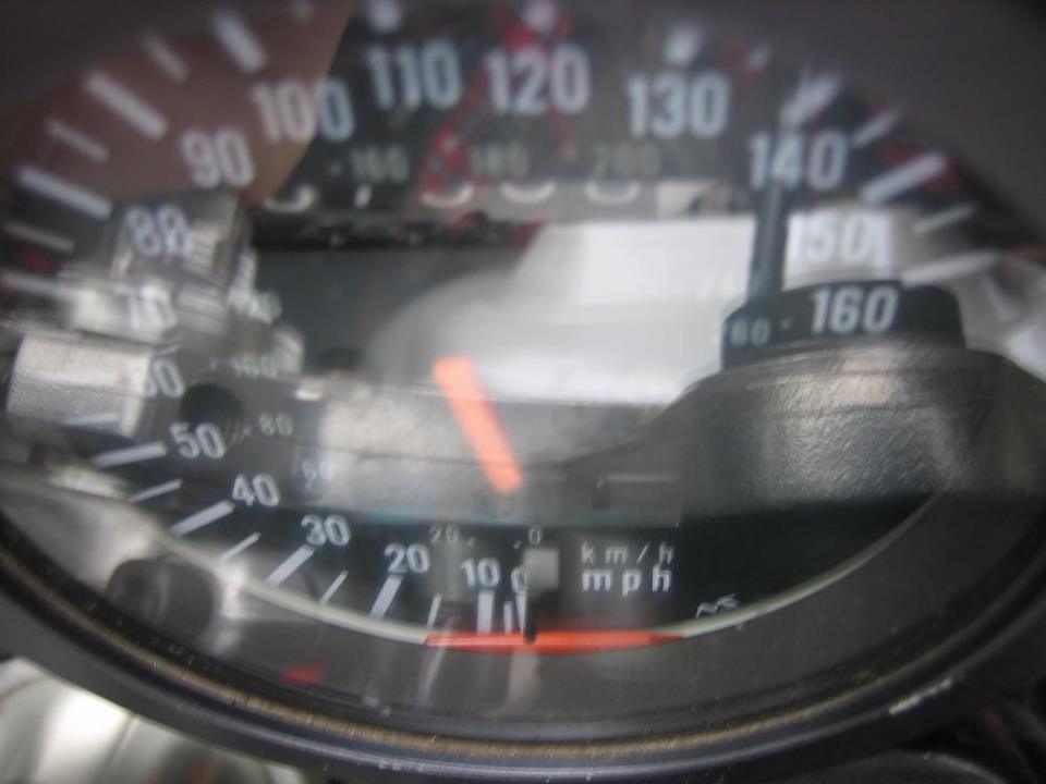
So I'm threaping along minding my own business and look down to be met with this - ...... which obviously fills me with joy. How does a speedo needle snap? Well, I guess fatigue from age, plastic don't last forever. So it needs mending. You can see the rest of the needle just at the bottom of the gauge but I suspect trying to glue it will not be successful. My questions are, does the speedo surround which retains the glass front just pull off (with a bit pf gentle persuasion)?; and does the needle simply push onto the spindle, allowing it to be replaced by another? I can get another speedo to cannibalise but before wrecking a good instrument I'll just ask if anyone has a needle kicking about, or a scrap speedo / tacho (needles look the same) for parts, available. Clock is for a GSXR750L but I suspect a few others may have the same needle.
-
Surely any camshaft lobe has to be case hardened or it would last all of five minutes? It may well not have an added hard chromed layer but that doesn't mean it is not case hardened in some way by the metal being surface treated.
-
Well done Clive, nice bike. I had to chuckle at the faces on the small gaggle of onlookers, they seemed totally WTF that some oil boiler could put out those sort of figures. I think you opened a few eyes there! As I said to one of them, the old ones are still the best
-
Rode through to spectate for a couple of hours in the early afternoon, spotted a few of the usual suspects from this parish. Nice day for it. TBH I expected a bit more from the hype before the event https://bikes.suzuki.co.uk/news/suzuki-announces-classic-bike-track-day-at-cadwell-park/ . Apart from the trackday riding there wasn't a great deal else to see and the paddock displays were rather smaller that you might have expected from the promo. But hey-ho, it was free to have a look and the ride there was nice enough. Saw someone's Old Skool turboed bike on the dyno mightily impressing the dyno man with I think he said 260bhp . Sounded awesome too. What seemed to really impress was the lovely power curve. Must be someone on here's bike? A FBM product?
-
I'd be a bit concerned about what the blowlamp heat might have done to the output shaft oil seal. It would be a tad annoying to put it all together, tighten on a new sprocket, then find you have to go up the hill again to get the nut off again to replace the seal. Cheap and easy job to change now if you have the slightest doubts.
-
Have you checked the valve clearances? Tight valves can lead to difficult hot starting.
-
Yeah, has to be something for the inner race of the bearings to clamp to on the inside, or else the tendency will be for the inner race to turn along with the outer race / wheel. The inner race should not turn around the spindle. I see that as item 2 on the fiche too.
-
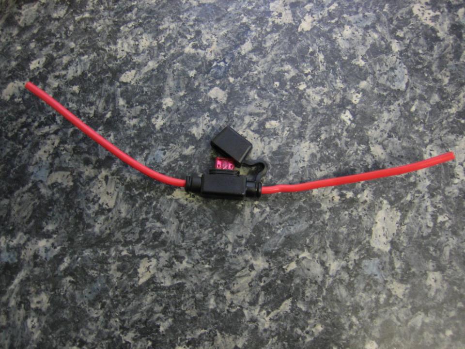
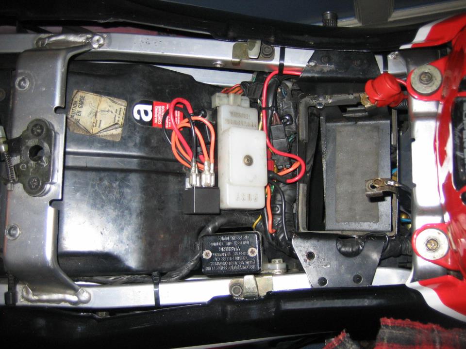
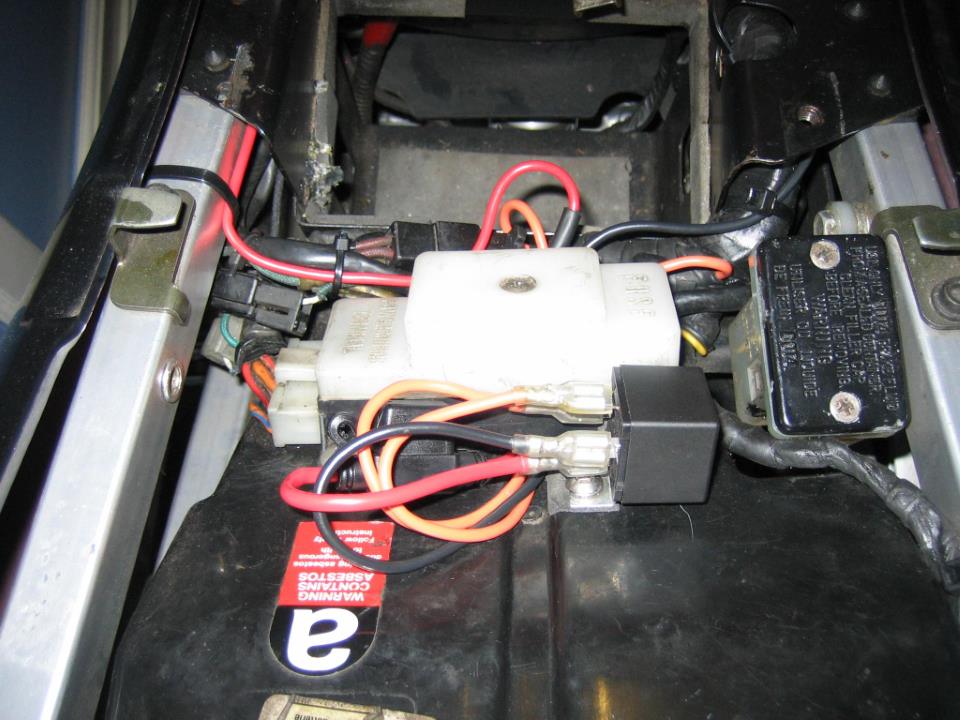
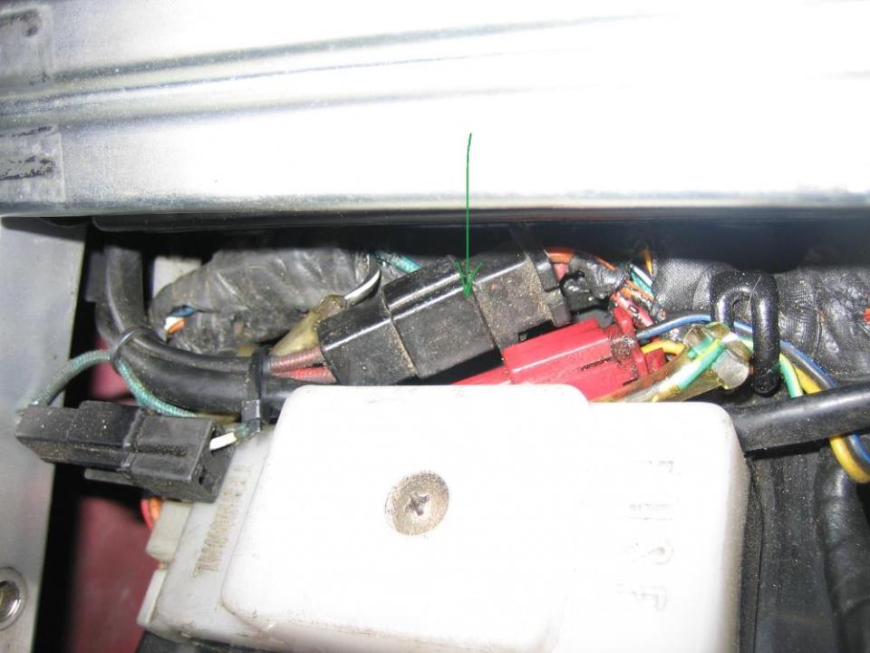
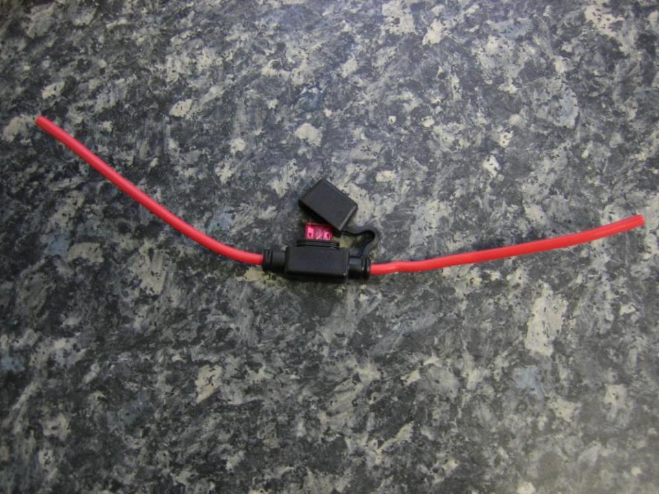
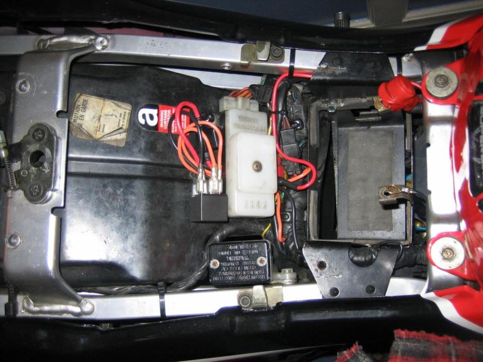
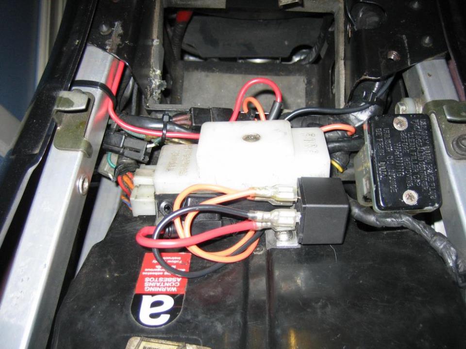
Having just done the charging mod described in the archive here https://oldskoolsuzuki.info/archives/tag/charging-system I thought it might be helpful to others if I described how I did it with a few pictures. I know some people find electrics daunting and a picture can be worth a thousand words. First of all, however, just to make clear that all credit for the mod goes to jonny1bump who posted it all up in the first place, all I'm doing is showing how I carried out his work on my bike. So first of all you need to find the connector block under the rider seat shown here arrowed in green - This has one red and one orange wire into it out of the loom and two reddish cloth covered wires out of it to the alternator. You need to cut the orange wire on the right - give yourself at least about an inch and a half of wire still coming out of the connector block, so you'll need to open up the loom a bit. DO NOT CUT THE RED WIRE, leave it alone. Now you need to splice in two new lengths of wire onto the cut ends. I used orange 3mm 30A rated thin wall insulation, as the closest match to the original. You don't want to be using thinner wire than the original - thinner wire = greater resistance = voltage drop and this is the problem you are trying to cure. You can crimp the wire on, personally I prefer a soldered splice, then seal the splice with heatshrink insulation On the other end you need to crimp on female spade connectors, which to match the terminals on your relay will most likely be 6.3mm. Use double crimped ones which grip the bare wire and the insulation. Again, as well as a crimp I like to put a bit of solder on my crimped end. I also slipped insulators on the wire to cover the blades to make everything 100% weathertight. Now you need to make up two more lengths of wire, same type as before but this time a black length and a red length. On one end of the black wire you want a double-crimped 6.4mm round battery terminal, on the other end a 6.3mm female spade with insulator. The red wire is slightly more involved as this mod bypasses the 30A circuit breaker in the original wiring, thus potentially leaving the positive feed to the trigger circuit unfused - but we're going to sort that. You want a 30A rated waterproof inline mini blade type fuseholder, which looks like this - The 30A rating is so that the integral wire tails it comes with will be the same rating and diameter as the rest of the wiring you are installing - again because you don't want to introduce thinner wire into the circuit. But you want a 10A fuse in it, don't put a 30A in it, that's way too high for this circuit alone. On one end of one of the wire tails fit a 6.3mm female spade with insulator. Extend the other tail by splicing on extra red wire and sealing the joint with heatshrink insulation. The female spade will attach to the relay and the end of the red wire will attach to the positive terminal of the battery, so measure things out and, before attaching a double-crimped 6.4mm round battery terminal, thread it through the terminal insulator on the battery cable, as this is easier than trying to fit it through with the terminal attached. When you've done that attach the terminal. The new terminals sit on top of the existing battery lead terminals. The relay I fixed to the undertray next to the fusebox as you can see. Drilled through the undertray and used a stainless nut and bolt to secure the relay bracket. I also put a bit of foam between the bracket and the undertray to provide a bit of damping but this might be overkill, as the plastic undertray is flexible anyway. I put another little bit of foam between the relay and the fusebox cover, so that is held firm and damped. You can see in the photo below how I've routed the wires, so you can follow this and cut to the required length before starting. I used the groove in the undertray as a duct for them to pass underneath the fusebox, which secures them neatly. The inline fuseholder is positioned between the relay connection and before the red wiring passes underneath the fusebox, so it's in a logical position close to the fusebox. The loom was resealed with self-amalgamating tape leaving the orange wires passing through. The red and black wires are cable tied to the battery wires, then cable tied along their length to the loom or frame. You don't want unsecured wires flapping about, they get fatigued over the years, work harden and then you get annoying internal cracks. A tidy bike is a reliable bike . So the wires go as follows - orange from the ignition switch side of the loom (i.e. from the right hand side as you're looking at the connector block in the first photo) goes to one of the coil terminals on the relay; black wire connects to battery negative and the other coil terminal on the relay; the other orange wire, from the alternator side of the loom (i.e. from the left hand side as you're looking at the connector block in the first photo) goes to one of the switch terminals on the relay; red wire connects to battery positive and the other switch terminal on the relay. I think the pictures below should illustrate this all clearly. Other ways of doing all this are available, this is just my take on the job.
- 79 replies
-
- 10
-

-
Thanks very much for posting that fix up, really appreciated. I've avoided cooking a battery yet. My first intimation something wasn't right is because my tickover went down with the lights on. Always been like it since I got the bike. Then came across the archive link, tested my voltages and found exactly the problem you described, so decided to nip things in the bud and do the mod. As you say in the fix, there must be loads of bikes out there with this issue, probably most of them, but if the battery lasts a few years before failing people just put it down to normal wear and tear.
-
But surely the Wemoto kit which #imago has in his ET disproves this statement? He based his reply on experience over a period of 2/3 years. Personally I've found Wemoto aftermarket stuff to be good quality.
-
https://oldskoolsuzuki.info/archives/tag/charging-system explains it all without me repeating it.
-
Cheers
-
Would have thought that would be easy enough to drill out the remains of the brass pipe in the casting and then push in the end of the existing pipe, glued in with something fuel resistant like Araldite. You'd want to put the glue on the outside of the pipe before pushing it in, not in the hole, or else you'll block the pipe end with glue, obv.
-
I'm going to do the charging circuit mod to my 750L as I have the high output voltage issue. Could someone help with a couple of questions, please? Firstly, in another thread Captain Chaos said that the connector block containing the required wires was located under the seat, so to sensibly locate the relay here - is this the one shown arrowed in the pic? It has red and orange wires coming in one end and a couple of reddish (old and faded) cloth insulation coloured ones out the other end. Second question - the 'how to' mentions a 30A relay but I'm guessing there is no requirement for the inserted lengths of wire to be thick 30A rated? Just the same size / rating as the wires to be cut? Does anyone know offhand what this size / rating is to save me buggering around trying to measure cut wires? Thanks.

-
You need a K&N sticker - adds at least 5bhp for pennies
-
Wemoto do Slinky Glide. Used them in an L, several thousand miles later still good.
-
GSXR slingshot M Steering damper - 1992 ( 91 model )
Crass replied to bertbuckie's topic in Oil Cooled
And if you do need a steering damper you can get a Toby damper to fit these bikes. Good quality and it's rebuildable, so it will last. It's worth bearing in mind that a steering damper is only second to a K&N sticker for increasing your speed . -
You've got the right part number there, which maybe suggests the carbs are not the originals for that bike, so the 1992 spec part is not correct?
-
Had to chuckle at the irony of a set of wheels mainly intended for slow moving Hogs being called 'chicane'
-
There must be a reasonable amount of difference though surely, as I thought that an 1100 motor in a 750 frame meant you couldn't get the rocker cover off, valve clearance time you need to take the motor out. Surely with an 1100 motor in an 1100 frame you don't need to do that so the frame must be different. Wasn't the steering geometry not different on the 11, suggesting the headstock angle is different? Personally I would think you would notice the 1100 frame on the road, hence why the popular mod is 7/11 to retain the better handling 750 frame - no?
-
It's off! I have my reservations about an electric impact shifting that one. Cut through nut a bit at a time, tried the breaker bar again - nowt. Repeat several times. Finally gave in when about 2mm of uncut nut remained, and then because the nut split. Replacement nut a few quid from breakers, so cheap solution.