Joseph
-
Posts
1,919 -
Joined
-
Last visited
Content Type
Profiles
Forums
Events
Everything posted by Joseph
-
Yes thats it, i have an idea to make a compact merger setup for a nicer integration of pipes 2 & 3, it adds work and complexity but it could work out ok. Space is always the issue Indeed having the turbo just after the manifold exit would be good but not possible here.
-
Thanks for all that info. Based on what you said (and what i can fit), if i build something similar to the photo i posted, it will be merging two 38s (from cyl 1 and 4) slightly stretched at the end to get to 51 with v band connector at the exit of the header, then a short length (around 45cm, can't do less) of 51 between the header and turbo. After that it would be 63 from the exit of the turbo to the rest of the exhaust system.
-
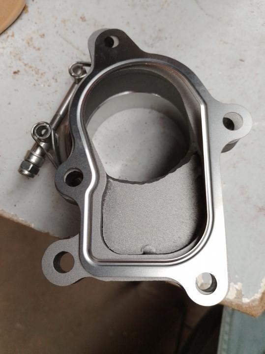
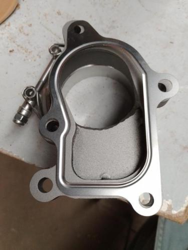
Another question and doubt heavy post. Right. So this is what i'll be working with : HE221 as you can see. Good deal made with someone who'd bought all this stuff for his diesel Mercedes before figuring out that it would be too small for his appliance. Looks like these Hoslets are the growing trend in good options for a 4 cylinder bike engine though. Beyond the damning fact that now that i have a turbo in hand, i have no idea where it can actually fit on the tricycle i'm building... ... I still need to dial it in. It now springs to obviousness why external wastegates are in some (most ?) cases, a great idea. My case potentially being one of them. Current orientation of the turbo inlets/outlets will need drastically changing to suit my needs. Is it correct to state that, as long as the bearing housing is horizontal (oil pathway therefore perfectly vertical), the turbine and compressor housing can point any which way i want ? However The vacuum unit setup and placement will then cause problems, because it is solidly bolted into the compressor, with the actuator rod of the vacuum unit set in a line towards the flapper. If i can rotate the compressor outlet to wherever I'd rather it be, if i make an outboard vacuum unit mount taken off the chassis for example, in order to retain current unit position, I should be good to go ? Thanks !
-
My bits were delivered with a 4 hole gasket for some reason ? So not sure whether it makes a difference
-
5.5 or 6 inch K rim will both fit the same, they both have that largely offset to the left rim center which is a bit of a job to sort out in an OSS but perfectly possible. 6 inch rim = more risk of chain to tyre contact though, so stick to a 5.5 600/750 rim like mentioned previously
-
Best to put them to use on a proper engine ?
-

Awesome 2-Stroke Pics
Joseph replied to banoffee's topic in Water Cooled, V-Twins, Singles and 2-strokes
-
Looking at the sump i'm actually not sure that baffling is possible or even necessary ? The pick up is very deep low down and cased in, and based on the fact that the oil sump level is actually 2 inches above the oil sump mating surface, it might take quite some G force cornering to empty the oil out of the pickup area. Anyways, not there yet, i'm currently looking at the header design. I've seen many online, basically a 4 into 1 with a flange plate for the turbo to bolt onto. Whats the general consensus on turbo headers ? NA engines need equal length tubes, some do tapered diameters etc, there's lots of potential in the header for those, but on a turbocharged setup how important is the header design ? Asking because i have space issues that i don't want to dig into too much, so if a very compact header is ok, i'll take it from there. Here is a photo of the header i had on that slabside : Two pairs of 90 degree bends from cylinders 1 and 4 into the turbo flange, and 2 pieces of straight pipe tapped into that from cylinders 2 and 3. Sounds alright ?
-
Aprillia Mille RSV wheels into Gen 1 Hayabusa
Joseph replied to Jonny's topic in Water Cooled, V-Twins, Singles and 2-strokes
Yes alignment can be achieved spot on. A 525 chain is what i'm using however mine is a slingshot frame with busa arm, not a full busa. I think i need a 5mm offset sprocket to do so, using an XR650 sprocket which is cheap and compatible/same splines. But overall it's not far off and judging by the chain run in the busa arm it can't be far off on a real busa either -
Isn't the 5 hole gasket just the 4 hole gasket with an extra tab and hole ?
-
The carrillos i've had in hand didn't look like that IIRC, and they were def the real deal, i'll see if i still have photos
-
Sounds like a decent turbo then I'm considering one for the 1400
-
How did it go ?
-
Aprillia Mille RSV wheels into Gen 1 Hayabusa
Joseph replied to Jonny's topic in Water Cooled, V-Twins, Singles and 2-strokes
Front shouldn't be a problem, i think the bearings are the same which is always good. I've put my rim on an SRAD fork very easily. Available in 310 and 320, and two offsets available for these italian discs, i need to check (i used the smaller offset i believe) but it ended up very nearly centering the discs in regards to the calipers, a single M10 washer between the caliper and fork did the trick. On the rear however it could be another matter. I'm fitting italian rims on a Gen.1 Busa swingarm, Hayabusa spindle is 28mm, the italian spindle is 30mm. In my case there doesn't seem to be an adaptable bearing with matching OD and ID to compensate the differences and make things fit together. I'm using 749 rims but chances are you need the same bearings in yours, and therefore will face the same issue. I have yet to find the best solution to put this together, as a result it's been put aside for the moment -
Guilty as (turbo)charged (although i had already mentioned that it wasn't due to go in a bike) Dry sump would indeed be perfect, not for the budget though. It would 100% need total home R&D and fabrication, i doubt anyone provides such equipment for this engine I'm hopeful that a sump baffle situation should be enough
-
Sorry got a bit mixed up. It looks like the turbo will be alongside the stator cover, perpendicular to the crank axis. It has to be a blow through system because a draw through would mean not having a steering column
-
Oh ? How so ? Height dependant technical requirements or just because of the layout ? In my case it looks like the turbo would/could be placed behind the gearbox casing/rear engine mount area
-
Back at it (somewhat) Onto turbo placement. Quick question : at what height in relation to the sump oil level can i potentially not require a scavenge pump ? Looks like i can plop the turbo on the frame approx 8 cm above the sump to engine mating surface
-
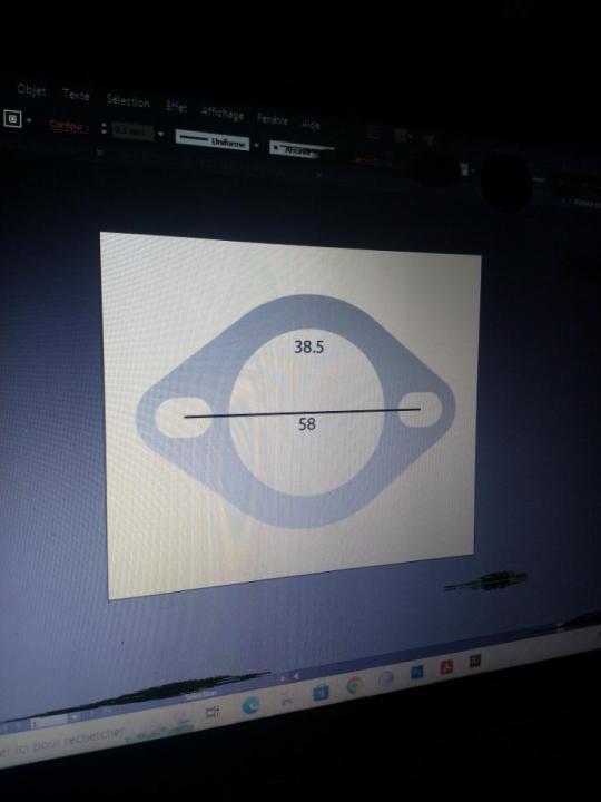
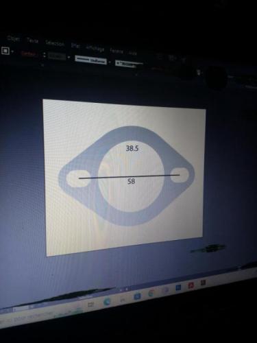
GSX 1400 and GSXR/bandit seem to have identical dimensions at the exhaust port (42 ID 58 spacing) at least on what i've compared in my garage
-
Here's what i had made, 54 to 62 bolt spacing :
-
Got the laser cut file for GSX 1400 exhaust flanges if you want since I had nothing with the engine i bought and obviously needed a set for the turbo header
-
The one i make is adjustable from -5 to +5
-
Cheap and cheerful :
-
Engine mods and other upgrades for a 92 GSXR 750?
Joseph replied to Upshotknothole's topic in Oil Cooled
It required quite an effort, the glue must be something like windshield glue, its very sticky and will stay on your skin, then the whole thing is hot so not great to hold tight. Then the trick is to lever it out without deforming the plastic frame which of course is warmed up and malleable. To be fair, when i did it, it was to put in that custom light and re fit the glass. In your case i'd heat it up to soften the glue enough, then put it in a bag, smash the glass with a heavy hammer and then you can easily take out the parts from the frame without putting too much pressure on the plastic -
Yes, the 34mm carbs have a single fuel inlet spigot cast into the body of carb no. 3 (i think) whereas on the following racks the fuel plugs into the pair of plastic t pieces that bridge each pair of carbs